Polarimetric scatterometry methods for critical dimension measurements of periodic structures

a periodic structure and critical dimension technology, applied in the field of optical measurement instruments, can solve the problems of further complications and less desirable results

Inactive Publication Date: 2005-08-11
TOKYO ELECTRON LTD
View PDF31 Cites 31 Cited by
  • Summary
  • Abstract
  • Description
  • Claims
  • Application Information

AI Technical Summary

Benefits of technology

[0017] The measurement head may be rotated by a motor-driven mechanism to orient the plane of incidence (and collection) to different azimuth orientations θ relative to the sample. This concept of a measurement head that can be rotated as a unit to different azimuth directions can be extended to other related instruments that have a non-normal incident beam or other directional anisotropies in their optics, including for example spectroscopic ellipsometers. In addition to employing non-normal incidence and collection, ellipsometers also include rotating compensators and analyzers which, like the polarimetric scatterometer, establish a specific polarization direction to the light. The ability to rotate the measurement head allows measurements to be made on wafers at any arbitrary orientation.

Problems solved by technology

Traditionally the inspection of CDs that are smaller than the wavelength of visible light has been done using large and expensive scanning electron microscopes.
The wafer might also rotate, but this is less desirable in systems without full X-Y movement that have a preferred measurement orientation with respect to certain wafer features.
The wafer may also be loaded into the measurement tool at an arbitrary angle creating further complications for instruments that have a preferred measurement orientation with respect to certain wafer features.

Method used


Image

  • Polarimetric scatterometry methods for critical dimension measurements of periodic structures
  • Polarimetric scatterometry methods for critical dimension measurements of periodic structures

Examples


Embodiment Construction

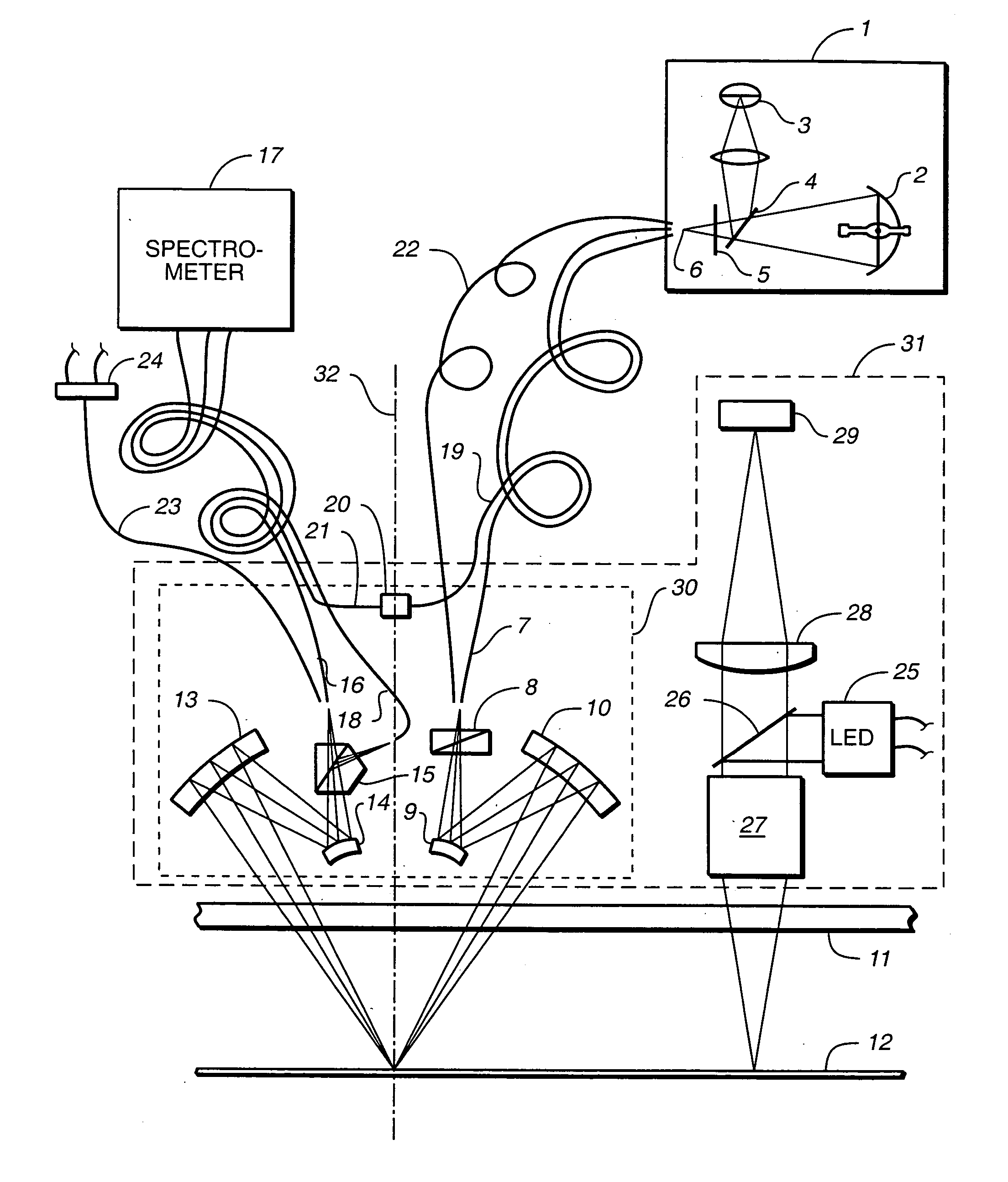
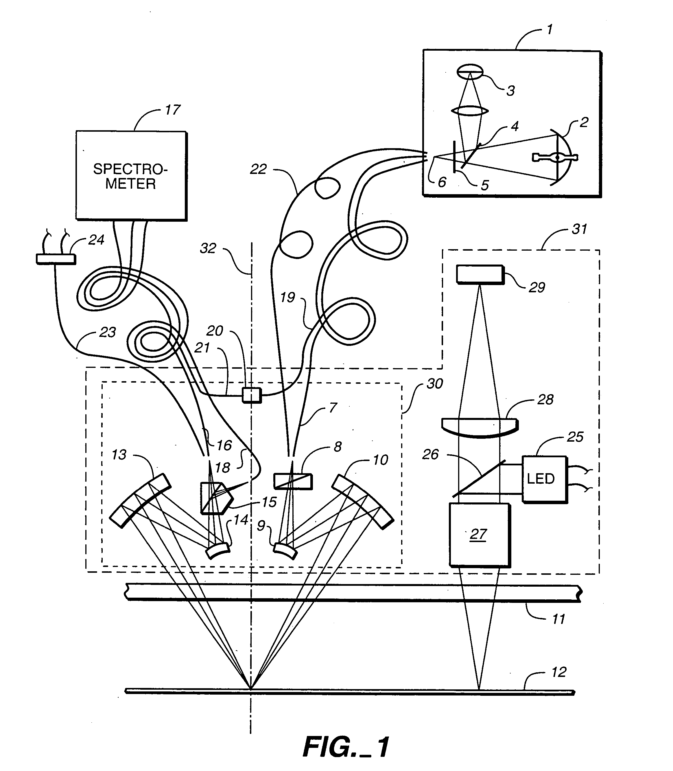
[0020] With reference to FIG. 1, the light box 1 has a high pressure xenon lamp 2 to provide illumination between 220 and 1100 nm. It also has a deuterium lamp 3 to provide deep-UV light between 190 and 240 nm. The shorter wavelength UV light helps give better results on smaller structures. A mirror 4 can be moved into the beam path to select between the two light sources. A shutter 5 can flip into the beam to cut off all light. The shutter both protects the optics from excessive UV light and allows measurement of the detectors' background signal. The light box optics create an image 6 of the sources that is large enough to illuminate several multi-mode optical fibers 7, 19 and 22. One of these fibers 7 preferably has a core diameter of 100 microns. The output end of fiber 7 is imaged onto the wafer 12 with a demagnification of approximately 2× using curved mirrors 9 and 10. The angle of incidence on the wafer is non-normal, i.e. greater than 40 away from perpendicular to the wafer ...


PUM

PropertyMeasurementUnit
azimuthal angleaaaaaaaaaa
core diameteraaaaaaaaaa
angle of incidenceaaaaaaaaaa

Abstract

An optical measurement system for evaluating a sample has a motor-driven rotating mechanism coupled to an azimuthally rotatable measurement head, allowing the optics to rotate with respect to the sample. A polarimetric scatterometer, having optics directing a polarized illumination beam at non-normal incidence onto a periodic structure on a sample, can measure optical properties of the periodic structure. An E-O modulator in the illumination path can modulate the polarization. The head optics collect light reflected from the periodic structure and feed that light to a spectrometer for measurement. A beamsplitter in the collection path can ensure both S and P polarization from the sample are separately measured. The measurement head can be mounted for rotation of the plane of incidence to different azimuthal directions relative to the periodic structures. The instrument can be integrated within a wafer process tool in which wafers may be provided at arbitrary orientation.

Description

CLAIM OF PRIORITY [0001] This application is a continuation of U.S. patent application Ser. No. 10 / 857,223 filed May 28, 2004, which is in turn a continuation of U.S. patent application Ser. No. 10 / 112,138, filed Mar. 29, 2002, which claims priority to U.S. Provisional Application No. 60 / 280,714, filed Mar. 30, 2001, incorporated herein by reference.TECHNICAL FIELD [0002] The present invention relates to optical measurement instruments and approaches for wafer testing during the manufacture of integrated circuits. BACKGROUND [0003] In the manufacture of integrated circuits, very thin lines or holes down to 100 nm or sometimes smaller are patterned into photo resist and then often transferred using an etching process into a layer of material below on a silicon wafer. It is extremely important to inspect and control the width and profile (also known as critical dimensions or CDs) of these lines or holes. Traditionally the inspection of CDs that are smaller than the wavelength of visib...

Claims


Application Information

Patent Timeline
Patent Type & Authority Applications(United States)
IPC IPC(8): G01N21/21G01N21/25G01N21/47G01N21/956
CPCG01B11/02G01J3/02G01J3/0294G01N21/211G01N2021/213G01N21/474G01N21/9501G01N21/956G01N21/25
Inventor NORTON, ADAM E.SEZGINER, ABDURRAHMANSTANKE, FRED E.
Owner TOKYO ELECTRON LTD
Why Eureka
Try Eureka