Suspension control apparatus

a suspension control and apparatus technology, applied in the direction of shock absorbers, bicycle equipment, instruments, etc., can solve the problems of prior art suffering a delay in changing the damping characteristics of the shock absorber, degrading the road holding capacity of tires, and affecting the effect of unsprung mass vibration damping control

Inactive Publication Date: 2005-08-18
HITACHI LTD
View PDF7 Cites 64 Cited by
  • Summary
  • Abstract
  • Description
  • Claims
  • Application Information

AI Technical Summary

Benefits of technology

[0013] According to the present invention, the damping characteristics of the damping characteristic inverting type shock absorber are controlled on the basis of a signal containing the contents of a detected signal from the unsprung mass vertical acceleration detecting device

Problems solved by technology

In addition, the conventional suspension control system estimates the piston speed (relative velocity) from the vertical acceleration of the sprung mass and suppresses unsprung mass vibrations (violent vibrations of the unsprung mass) on the basis of the estimated relative velocity, thereby minimizing high-frequency noise to the occupants of the vehicle and the degradation of ti

Method used


Image

  • Suspension control apparatus
  • Suspension control apparatus
  • Suspension control apparatus

Examples


first embodiment

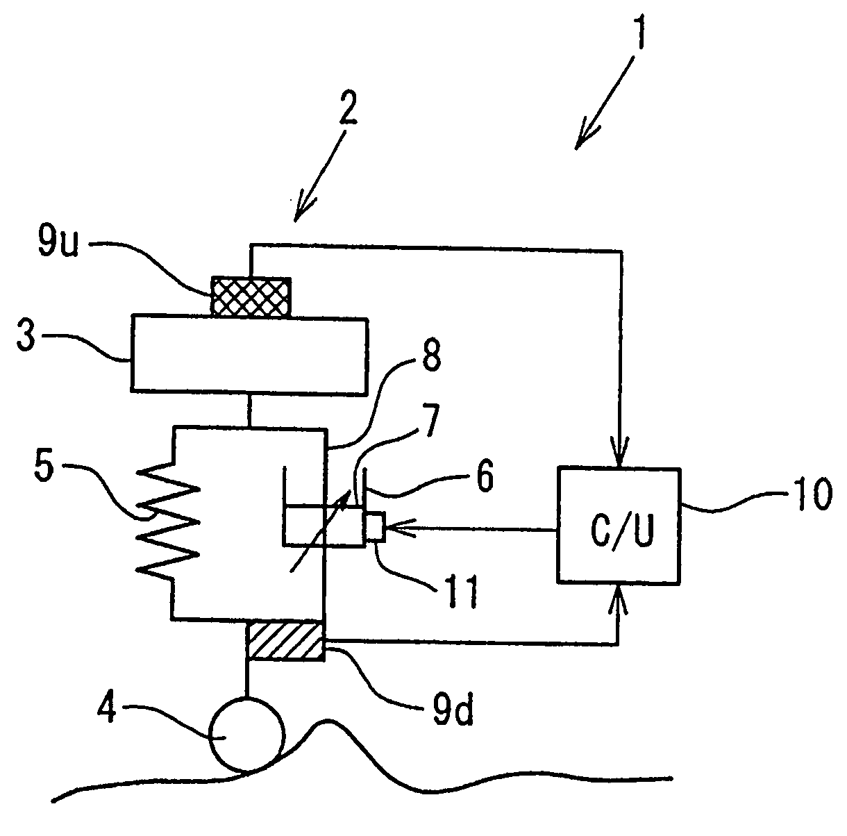
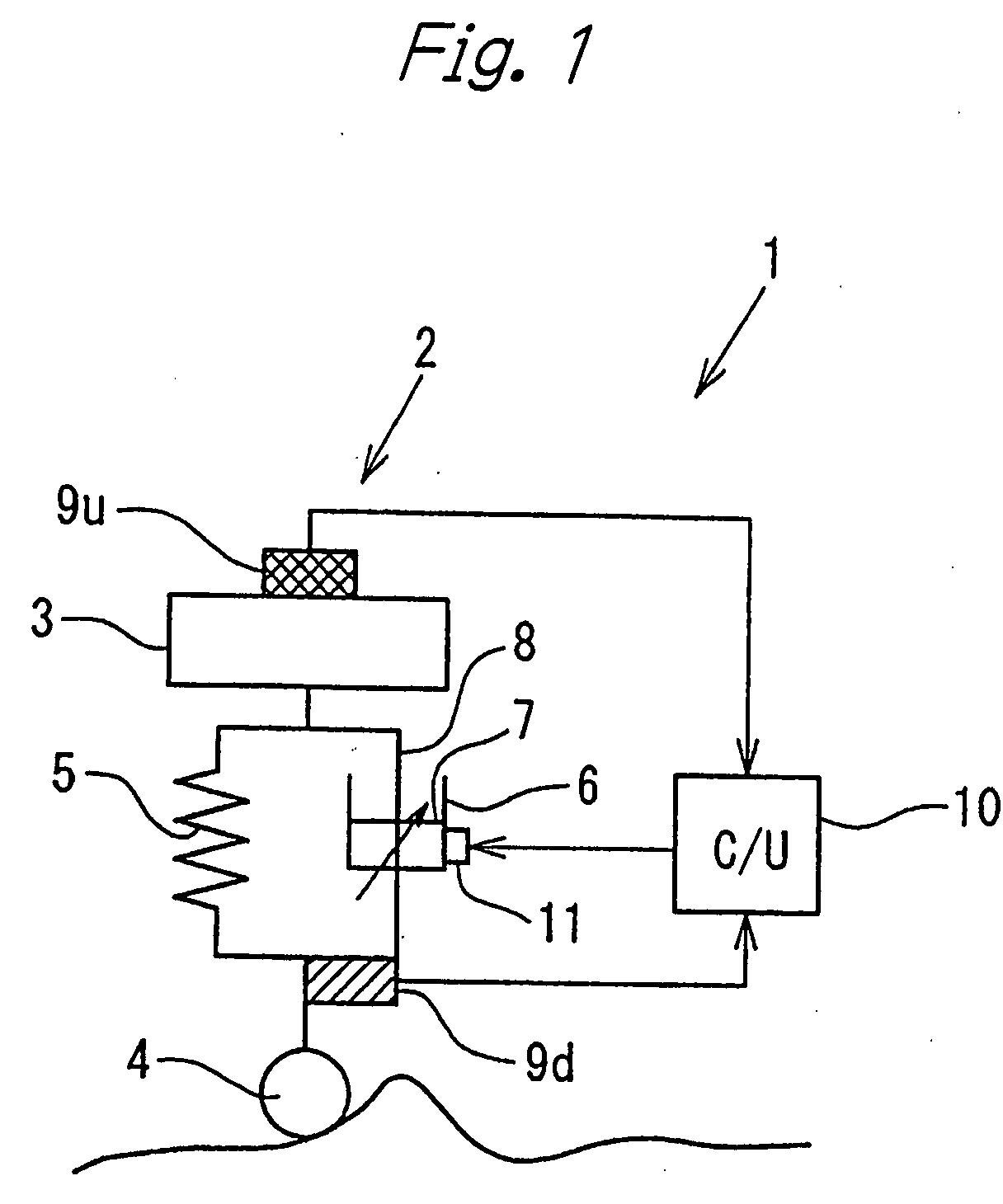
[0048] A suspension control system 1 according to the present invention will be described below with reference to FIGS. 1 to 4. In FIG. 1, a spring 5 and a damping characteristic adjustable shock absorber 6 (damping characteristic inverting type shock absorber) are interposed in parallel between a vehicle body 3 (sprung mass member) and each of four wheel(4)-side structures (only one of them is shown in the figure), which constitute an automobile 2 (vehicle). The wheel(4)-side structure is an unsprung mass member (hereinafter occasionally referred to as simply “unsprung mass”) including a shock absorber mounting bracket on an axle, etc. The spring 5 and the shock absorber 6 support the vehicle body 3. The shock absorber 6 has a piston 7 movably accommodated therein. A piston rod 8 connected to the piston 7 is held by the vehicle body 3. The shock absorber 6 is held by a wheel(4)-side structure (including a shock absorber mounting bracket, etc.).

[0049] A sprung mass acceleration sens...

second embodiment

[0074] Next, a suspension control system 1A according to the present invention will be described with reference to FIGS. 13 to 19. It should be noted that members equivalent to those shown in FIGS. 1 to 12 are denoted by the same reference symbols used in FIGS. 1 to 12, and a description thereof is omitted.

[0075] The controller 10A of the second embodiment has, as shown in FIG. 13, a relative acceleration calculating section 25, a road surface condition judging section 30, and a road surface condition judging map storage section 32. The road surface condition judging section 30 detects a road surface condition (“undulating road”, “ordinary road”, or “rough road”) on the basis of the sprung mass acceleration αu. The storage section 32 previously stores a road surface condition judging map 31 that the judging section 30 uses to judge a road surface condition. The road surface condition judging section 30 adjusts the magnitude of the control gain Kd of the amplifier circuit 21 to corre...

third embodiment

[0101] Next, a suspension control system 1B according to the present invention will be described with reference to FIGS. 20 to 26.

[0102] As shown in FIGS. 20 and 21, the suspension control system 1B has a vehicle speed sensor 40 for detecting the vehicle speed of an automobile 2 equipped with the suspension control system 1B. Detected vehicle speed data is input to a controller 10B. The controller 10B calculates a period of time elapsed from the time a front wheel has passed a point on the road surface until a rear wheel has passed the same point (expected transit time =wheelbase / vehicle speed) on the basis of the vehicle speed data and the wheelbase of the automobile 2. When the expected transit time has elapsed from the time the front wheel passed the point on the road surface, the controller 10B controls the shock absorber 6 for the rear wheel in accordance with the road surface condition at that point, thereby effecting favorable suspension control for the rear wheel and hence t...


PUM


Abstract

In a suspension control system according to the present invention, a sky-hook command signal B obtained from velocity data obtained by integrating a sprung mass acceleration αu from a sprung mass acceleration sensor 9u and an unsprung mass vibration damping command signal C obtained on the basis of an unsprung mass acceleration αd detected by an unsprung mass acceleration sensor 9d are added together to obtain a control signal A for a damping characteristic inverting type shock absorber 6. The control signal A reflects the unsprung mass acceleration αd that leads in phase by 90° the piston speed. Accordingly, it is possible to compensate for a response delay due to an actuator 11, etc.

Description

BACKGROUND OF THE INVENTION [0001] The present invention relates to a suspension control system having a damping characteristic inverting type shock absorber for use in vehicles such as automobiles and railway vehicles. [0002] One example of conventional suspension control systems having a damping characteristic inverting type shock absorber is disclosed in Japanese Patent Application Unexamined Publication (KOKAI) No. 2002-321513. [0003] The suspension control system disclosed in the above-mentioned publication operates to damp vibrations of the sprung mass (vehicle body) as follows. When the vehicle rides over an upward swelling of undulation in the road surface, for example, the suspension control system provides “soft” damping characteristics for the compression stroke, thereby suppressing the upward movement of the vehicle body as it is pushed up. Meanwhile, “hard” damping characteristics are provided for the extension stroke. Therefore, when the vehicle goes down the undulatio...

Claims


Application Information

Patent Timeline
IPC IPC(8): F16F7/10
CPCB60G17/016B60G2800/916B60G17/08B60G2400/102B60G2400/206B60G2400/821B60G2400/91B60G2500/10B60G2600/02B60G2600/14B60G2600/16B60G2600/17B60G2600/184B60G2600/1877B60G2600/60B60G2600/604B60G2800/162B60G17/018
Inventor UCHINO, TORUICHIMARU, NOBUYUKIUCHIYAMA, MASAAKI
Owner HITACHI LTD
Why Eureka
Try Eureka