Superheated vapor generator

a superheated vapor and generator technology, applied in the direction of electric/magnetic/electromagnetic heating, lighting and heating apparatus, etc., can solve the problems of long heating time, low heating efficiency of superheated vapor generators, and less durable superheated vapor generators including heating elements buried in non-magnetic materials as coating materials, etc., to increase the efficiency of superheated vapor generation, reduce passage resistance, and simple to form

Inactive Publication Date: 2005-08-18
NEPUREE CORP
View PDF4 Cites 29 Cited by
  • Summary
  • Abstract
  • Description
  • Claims
  • Application Information

AI Technical Summary

Benefits of technology

[0023] The vapor passages of the heating medium may be a number of arcuate spaces defined by a combination of coaxial cylinders having different diameters. The arcuate spaces are simple to form by combining coaxial cylinders of various sizes. The arcuate passages make it possible to reduce the passage resistance exerted to the saturated vapor being heated acceleratively in them. The resistance reduction is effective in increasing the efficiency of superheated vapor generation.
[0024] The walls of the coaxial cylinders may be thicker toward the periphery of the heating medium. In this case, the induction field intensity in the superheated vapor generator is so distributed that more magnetic fluxes are canceled toward the axis of the turns of the high frequency induction heating coil, while more magnetic fluxes pass through and near the outer cylindrical surface of the heating medium. It is possible to take advantage of this surface effect on magnetic fluxes by making the cylinder walls thicker toward the periphery of the heating medium. This makes it easy to induce eddy currents in the heating medium, thereby increasing the heating efficiency of the medium.
[0025] The radial dimensions of the arcuate spaces may be equal or larger toward the periphery of the heating medium. In this case, by setting the radial dimensions at a predetermined value or larger toward the periphery of the heating medium, it is possible to increase the areas of outer vapor passages of the medium, where the surface effect on magnetic fluxes enable more efficient heating. This enables efficient generation of superheated vapor.
[0026] The material for the heating medium may be porous silicon carbide. This makes it possible to form passages for induction heating and as the passage structure out of the single material. The functi

Problems solved by technology

Accordingly, the heating/conducting area of these generators is narrow, so that their heating efficiency is low, and so that their heating time is long.
In particular, the vapor generator in which paraffin can be heated to heat a spiral pipe cannot generate superheated vapor with a high temperature, which may be 500° C. These vapor generators are not suitable for multi-purpose heating because they cannot generate sufficiently dry vapor but are liable to generate wet steam.
The superh

Method used


Image

  • Superheated vapor generator
  • Superheated vapor generator
  • Superheated vapor generator

Examples


embodiment 1

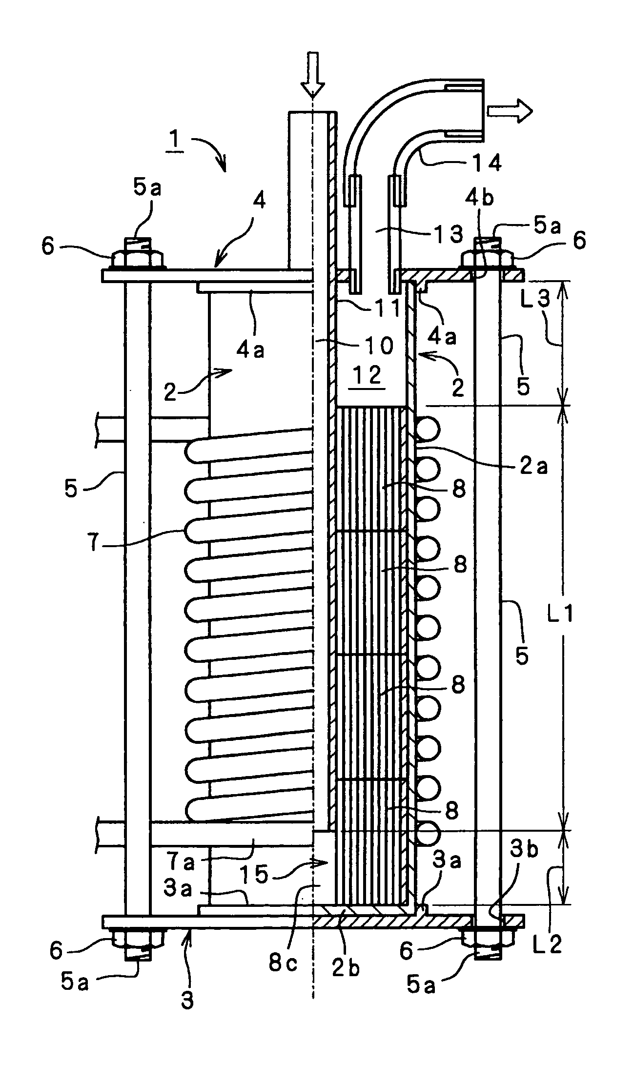
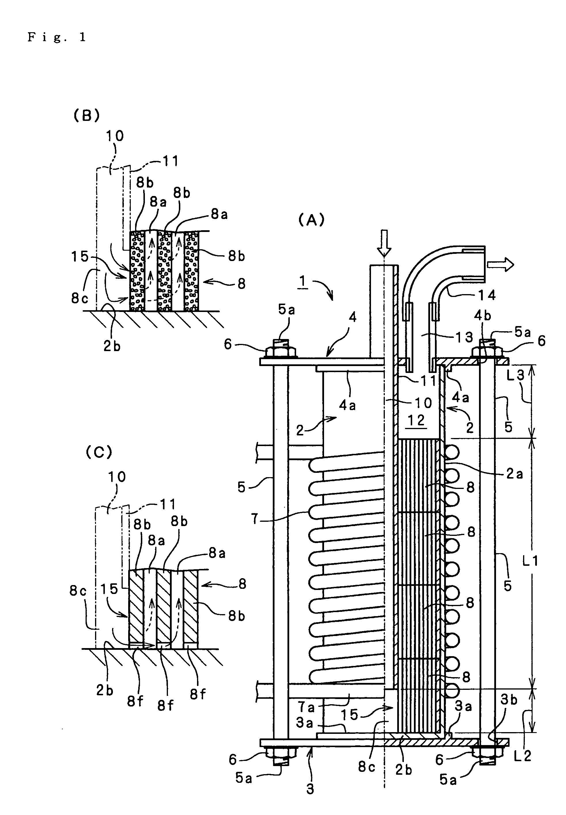
[0035]FIGS. 1-3 show superheated vapor generators according to a first embodiment of the present invention.

[0036] The superheated vapor generator 1 shown in FIGS. 1(A)-1(C) includes a vertically extending cylindrical container 2. The cylindrical container 2 consists of a cylindrical wall 2a and a bottom plate 2b, which closes the bottom of the wall. The cylindrical container 2 stands on a lower support plate 3 in the form of a disc, which has a circular support ring 3a formed on its upper side. The support ring 3a engages with the bottom periphery of the cylindrical container 2 to fix it horizontally. The cylindrical container 2, support plate 3 and support ring 3a are coaxial or concentric.

[0037] The open top of the cylindrical wall 2a of the cylindrical container 2 is closed by an upper support plate 4 in the form of a disc, which has a circular support ring 4a formed on its lower side. The support ring 4a engages with the top periphery of the cylindrical container 2 to fix it h...

embodiment 2

[0098] FIGS. 4(A)-4(C) show a superheated vapor generator according to a second embodiment of the present invention.

[0099] Each heating element 8 of this embodiment includes a number of coaxial cylinders 8d having different diameters. The cylinders 8d are fixed together by radial partitions 8e. Vapor passages 8a are formed between the cylinders 8d and between the partitions 8e. The vapor passages 8a are arcuate in radial section and equal in radial size. The heating element 8 in the shape shown in FIGS. 4(A)-4(C) is molded out of a porous silicon carbide material. Otherwise, this embodiment is similar to the first embodiment. Similar parts of the two embodiments are assigned the same reference numerals.

[0100] The vapor passages 8a are arcuate spaces defined by the coaxial cylinders 8d having different diameters. The arcuate spaces are simple to form by combining cylinders 8d of different sizes. The arcuate passages make it possible to reduce the passage resistance exerted to the s...

embodiment 3

[0101] FIGS. 5(A) and 5(B) show a superheated vapor generator according to a third embodiment of the present invention.

[0102] Each heating element 8 of this embodiment is similar to that of the first embodiment, but the walls of its coaxial cylinders 8d are thicker toward the periphery of the element 8. For example, the walls of the outermost, second outermost and innermost cylinders 8d have thicknesses T1, T2 and Tn, respectively, and are thinner toward their axis. Alternatively, the walls of every two or more adjacent cylinders 8d might be thinner toward their axis. For example, the walls of the outermost two cylinders 8d and second outermost two cylinders 8d might have thicknesses T1 and T2, respectively. In this example, the arcuate spaces are larger in radial size toward the periphery of the heating element 8. Otherwise, this embodiment is similar to the foregoing embodiments. Similar parts of the three embodiments are assigned the same reference numerals.

[0103] As stated abo...


PUM


Abstract

A superheated vapor generator has a tubular, vertically extending container with closed ends. A high frequency induction heating coil is wound around the container. A heating medium is placed in the container and is made from material heatable by electromagnetic conduction. A number of vapor passages extend through the heating medium longitudinally of the tubular container. The tubular container has a heating section with the heating coil and a non-heating section under the heating section. Material for superheated vapor is supplied through a supply passage from a position above the heating medium to the non-heating section. A passage structure is provided in the non-heating section for flow of material supplied through the supply passage therethrough into the vapor passages of the heating medium. A discharge passage is formed above the heating medium. A discharge passage is formed above the heating medium for discharging superheated vapor.

Description

FIELD OF THE INVENTION [0001] The present invention relates to a superheated vapor generator for use in various fields. In particular, the invention relates to a superheated vapor generator that can generate superheated vapor in a wide temperature range, which may be 120° C.-700° C. The vapor generator can be used as, in or with thermal processing equipment for cooking, boiling, steaming, roasting, broiling, toasting, smoking, drying, sterilization, dezymotization, dissolution, fusion, melting, deposition, welding, cleaning, blowing, humidification, air conditioning, or the like. BACKGROUND OF THE INVENTION [0002] A conventional superheated vapor generator includes a drum made of metal or other magnetic material. Water or saturated steam is introduced into the drum, which is inductively heated. Another conventional superheated vapor generator includes a drum made of non-magnetic material, in which a magnetic material is buried. Still another conventional superheated vapor generator ...

Claims


Application Information

Patent Timeline
IPC IPC(8): F22B1/28F25D23/00H05B6/10
CPCF22B1/281B24B49/105F22B1/28H05B6/10
Inventor WAKAMATSU, TOSHIOKANOU, TSUTOMUOGIHARA, MASANORI
Owner NEPUREE CORP
Why Eureka
Try Eureka