Memory management method, image processing apparatus, and memory management program

Inactive Publication Date: 2005-08-18
SONY CORP
View PDF12 Cites 21 Cited by
  • Summary
  • Abstract
  • Description
  • Claims
  • Application Information

AI Technical Summary

Benefits of technology

[0024] As described above and according to the invention, each of a plurality of image processing section is able to access a corresponding memory area to read or write image data by simply specifying memory area information without managing use status of each memory area by recognizing its address in an image memory. In addition, memory areas corresponding to image size are individually allocated in the image memory, so that, if a change occurs

Problems solved by technology

Besides, the encoder 21 and the decoder 31 must manage the allocated memory areas by always recognizing their physical addresses, thereby complica

Method used


Image

  • Memory management method, image processing apparatus, and memory management program
  • Memory management method, image processing apparatus, and memory management program
  • Memory management method, image processing apparatus, and memory management program

Examples


first embodiment

The configuration of a First Embodiment

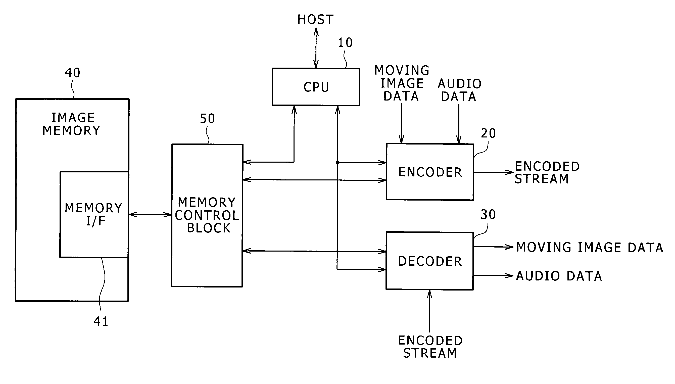
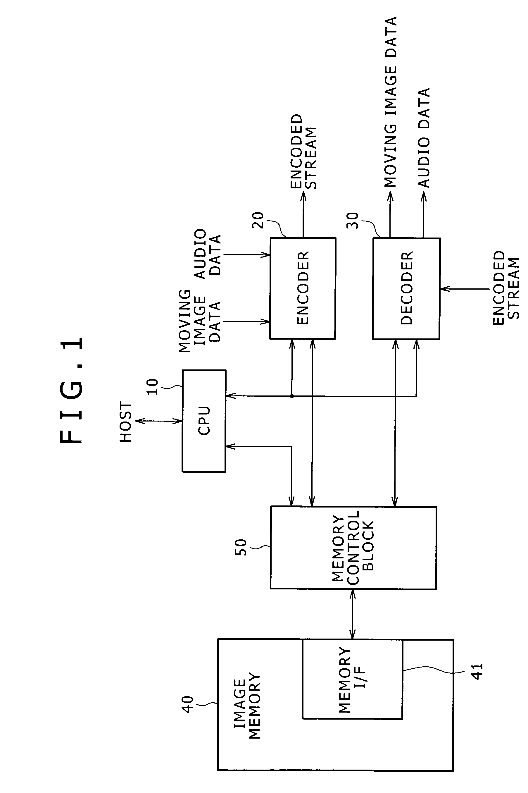
[0052] With the first embodiment, an example is assumed in which the present invention be applied to an image processing apparatus that encodes and decodes moving image and audio signals in accordance with a predetermined data compression encoding system. Now, referring to FIG. 1, there is shown an exemplary configuration of the main portion of an image processing apparatus practiced as the first embodiment of the invention.

[0053] The image processing apparatus shown in FIG. 1 is arranged in an image recording / reproducing apparatus or an imaging apparatus having a function of encoding inputted moving image data and audio data by a data compression encoding system such as MPEG to record the encoded data to various types of recording media and a function of decoding data recorded to various types of recording media to reproducibly output decoded moving image data and audio data, for example. This image processing apparatus is adapted to concurre...

second and third embodiments

[0320] Referring to FIG. 23, there is shown a block diagram illustrating an exemplary configuration of the main portion of an image processing apparatus practiced as a second embodiment of the invention.

[0321] In the image processing apparatus shown in FIG. 23, encoding can be concurrently executed by two encoders 20a and 20b. For example, the same moving image data such as taken image data and the same audio data are supplied to the two encoders 20a and 20b to make these encoders encode the supplied data with different image sizes, one encoded stream being recorded to a magnetic tape, while the other encoded stream being recorded to another type of recording medium such as a memory card or transmitted to an external device via a network.

[0322] As with the first embodiment, the encoder 20a and 20b access the image memory 40 through the memory control block 50 in the image processing apparatus shown in FIG. 23. This configuration allows the changing of the image size with one encod...


PUM


Abstract

When encoding and decoding are concurrently executed by sharing one image memory, the present invention is able to flexibly cope with a situation in which a change occurs in the image size subject to processing. A memory allocation processing block receives information about the image size and the number of images that are specified for each of encoding and decoding, individually allocates the memory areas corresponding to the specified image size by allocating these memory areas to the free area in the image memory in the number equivalent to the number of images, and outputs the addresses of the allocated memory areas. A memory area management block holds memory area information in which the correlation between the identification information of each allocated memory area and the access information for accessing each memory area and receives the requests from the encoder and the decoder for using the allocated memory areas and returning the used memory areas, thereby managing the use status of each memory area on the basis of the memory area information.

Description

BACKGROUND OF THE INVENTION [0001] The present invention relates to a memory management method, an image processing apparatus based on this memory management method, and a memory management program for concurrently executing processes by a plurality of image processing section by sharing one image memory between these image processing section. [0002] Recent advancement in image compression technologies such as MPEG (Moving Picture Experts Group) makes it a general practice to digitize image signals and handle digital image signals. For example, digital video cameras for taking moving images and recording them as digital data are in wide use. [0003] Some recently developed digital video cameras have two kinds of recording media, for example, the magnetic tape and the memory card comprised of the removable semiconductor memory, in one body. May of these digital video cameras have a function of concurrently executing the encoding and decoding of moving image and the two lines of encodi...

Claims


Application Information

Patent Timeline
IPC IPC(8): G06T1/60G06F12/02H04N5/907H04N5/92H04N19/00H04N19/423
CPCH04N19/127H04N19/436H04N19/423H04N19/136B43L19/0056G06C1/00
Inventor OKADA, TETSUYA
Owner SONY CORP
Why Eureka
Try Eureka