Raman assisted EDFA system and method

a technology of edfa and raman, applied in the field of optical telecommunications systems, can solve the problems of amplitude distortion, limited maximum distance optical signals can travel through optical fiber before degrading to the point of being undetectable by a receiver, and difficulty in maintaining appropriate gain and low noise, so as to reduce the increase of noise accumulation

Inactive Publication Date: 2005-08-18
TYCO ELECTRONICS SUBSEA COMM LLC
View PDF10 Cites 10 Cited by
  • Summary
  • Abstract
  • Description
  • Claims
  • Application Information

AI Technical Summary

Benefits of technology

[0011] Accordingly, the present invention generally provides a system including distributed Raman assisted EDFA's to reduce the increased noise accumulation associated with long and inconsistent terrestrial spans but maintain the appropriate gain from each amplifier.
[0014] In another preferred embodiment, the Raman portion is configured to provide variable gain, such that the EDFA gain portion has a substantially constant input power. Preferably, the Raman amplifier variable gain ranges from about 1 to 16 dB. Most preferably the maximum Raman gain is about 14 dB. In yet another preferred embodiment, the optical attenuator reduces power from an output of the EDFA gain portion. Most preferably, the attenuator reduces power in 1 dB increments.
[0015] Thus, in accordance with this aspect of the present invention, a hybrid amplifier is provided that includes a variable Raman gain source for optimizing the amplifier so that the overall effect of noise accumulation and multi-path interference (caused by multiple Rayleigh scattering) is minimized.
[0018] Several important advantages will be appreciated from the foregoing summary. For example, the EDFA benefits from forward pumping and is capable of taking full advantage of the Raman assist. That is, in combination with variable Raman gain, all the spans are operated with optimum launch powers into longer lossier spans, with an improvement in noise performance and minimal nonlinear effects.
[0019] As another advantage, the present invention allows for a single EDFA design to be used, in combination with Raman variable gain, in a system having spans ranging from 30 km to 110 km. This allows for the use of one type of amplifier as a generic building block for terrestrial ULH systems having varying spans.

Problems solved by technology

The maximum distances optical signals can travel through optical fiber before degrading to the point of being undetectable by a receiver is limited by, among other things, power loss or attenuation caused by dispersion, scattering, absorption and bending.
After propagation over a given distance, shorter wavelengths may overtake and become superimposed on longer wavelengths causing amplitude distortion.
Amplifying ULH terrestrial transmission systems and maintaining appropriate gain and low noise, by contrast, is somewhat more challenging.
For example, ULH terrestrial systems are plagued with large span loss variations and daily and seasonal temperature fluctuations.
Furthermore, unlike custom built submarine systems, terrestrial systems often have to be designed using existing fiber in the ground, unmatched and with unknown fiber characteristics.
The associated span loss is very high and inconsistent.
In ULH systems, the longer spans generally cause increased noise accumulation.
Similarly, the nonlinearities limit the amount of power that can be launched into the next NZ-DCF span.
This complicates the EDFA design and may potentially degrade performance.

Method used


Image

  • Raman assisted EDFA system and method
  • Raman assisted EDFA system and method
  • Raman assisted EDFA system and method

Examples


Embodiment Construction

[0027] Reference will now be made in detail to the present preferred embodiments of the invention, an example of which is illustrated in the accompanying drawings.

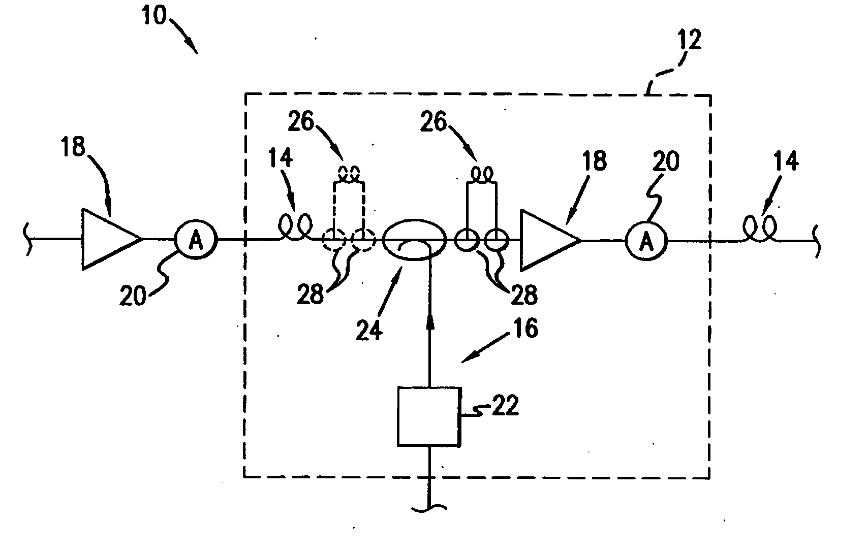
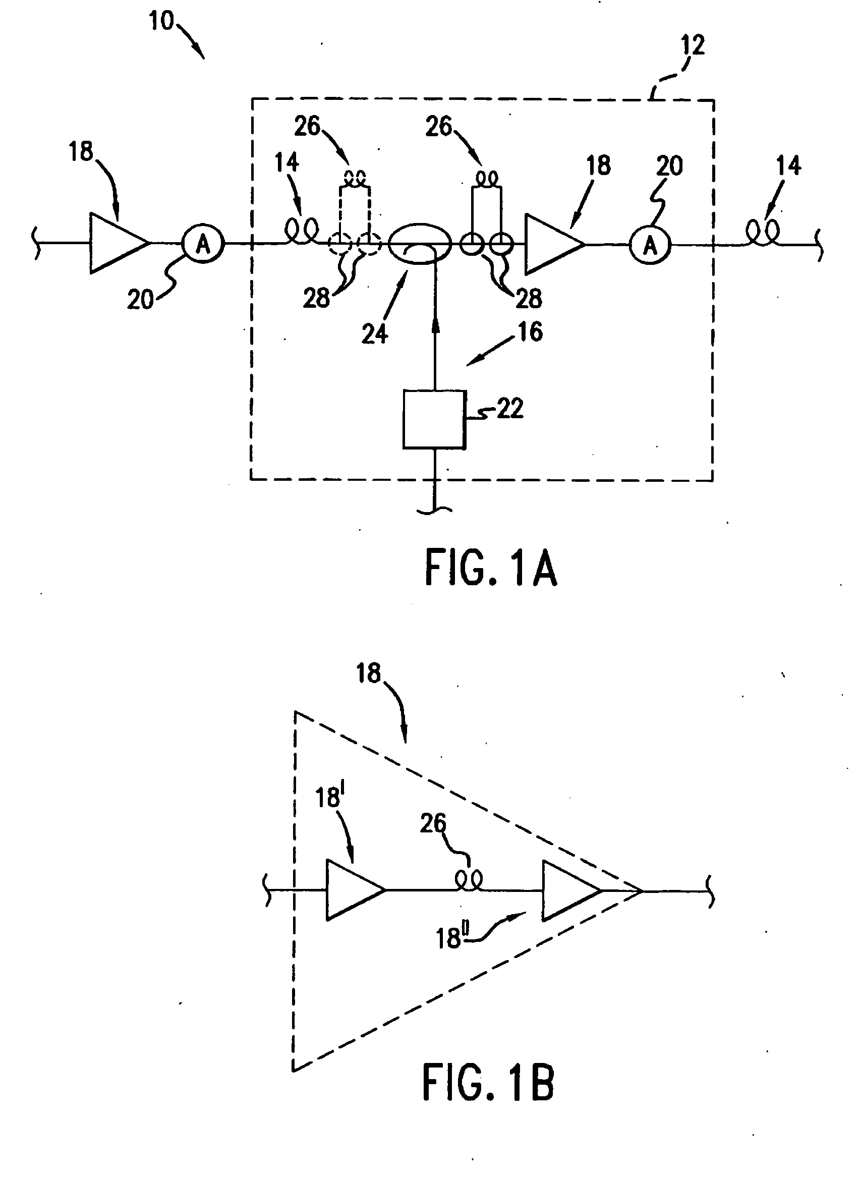
[0028] An exemplary embodiment of the present invention is shown in FIG. 1A and is designated generally by reference numeral 10. As embodied herein and referring to FIG. 1, a portion of an optical communication system 10, including at least one Raman assisted EDFA hybrid amplifier 12. The hybrid amplifier includes transmission fiber 14, a Raman gain source 16, an EDFA gain source 18, and an optical attenuator 20. The Raman gain source 16 includes a Raman pump module 22, having one or more Raman wavelengths. Each can be independently adjustable through separate attenuators or through bias adjustments. In this preferred embodiment, the Raman gain source 16 is coupled to the transmission fiber 14 by way of coupler 24. The coupler may be any known type such as a WDM module or a 3 dB device. The Raman gain is introduced into t...


PUM


Abstract

A system, amplifier and method are provided for amplifying an optical signal in an optical communications system where spans between amplifiers may vary. The system includes a Raman amplifier variable gain portion and an EDFA gain portion. The amount of Raman amplifier gain is chosen to trade off accumulation of noise with accumulation of multi-path interference. This variable Raman gain is used to equalize the loss of each span so that the amount of optical power supplied at the input of the EDFA gain portion is substantially constant throughout the system.

Description

CROSS REFERENCE TO RELATED APPLICATIONS [0001] The present application claims the benefit of U.S. Provisional Appl. Ser. No. 60 / 249,346 filed Nov. 16, 2000, entitled “Amplifier Design for Raman Assisted EDFA Systems,” the teachings of which are herein incorporated by reference, and the present application herein incorporates by reference the teachings of commonly assigned U.S. Provisional Appl. Ser. No. 60 / 249,347, also filed Nov. 16, 2000, entitled “Terrestrial System Design,” and its related U.S. patent application Ser. No. ______, being filed concurrently with the present patent application.FIELD OF THE INVENTION [0002] The present invention relates to optical telecommunications systems. More particularly, the present invention relates to Raman assisted EDFA amplification in long haul and ultra-long haul optical telecommunications systems. BACKGROUND OF THE INVENTION [0003] The maximum distances optical signals can travel through optical fiber before degrading to the point of bei...

Claims


Application Information

Patent Timeline
Patent Type & Authority Applications(United States)
IPC IPC(8): H04B10/12H04B10/17
CPCH04B2210/003H04B10/2916
Inventor NISSOV, MORTENPILIPETSKII, ALEXEI N.GOLOVCHENKO, EKATERINANAGEL, JONATHANTEN, SERGEY
Owner TYCO ELECTRONICS SUBSEA COMM LLC
Why Eureka
Try Eureka