Miniaturized fluid delivery and analysis system

Active Publication Date: 2005-08-18
AST MANAGEMENT
View PDF4 Cites 123 Cited by
  • Summary
  • Abstract
  • Description
  • Claims
  • Application Information

AI Technical Summary

Benefits of technology

[0015] Another aspect of the invention provides a pump structure comprising a first substrate, a second substrate and a flexible intermediate interlayer. The flexible intermediate interlayer is sealedly interfaced between the first substrate and the second substrate. The pump structure further comprises a pump chamber, as well as a fluid flow controlling structure, formed in the first substrate and the second substrate, thereby restricting a flow of a fluid through said pump chamber to a first direction. The pump structure further comprises a linear actuator for providing a pumping action in the pump chamber to pump the fluid to flow. The pump chamber has a substrate chamber formed in the first substrate as well as a hole formed in the second substrate to free the flexible intermediate interlayer to act as a pump interlayer diaphragm. The linea

Problems solved by technology

Such pumping structures are

Method used


Image

  • Miniaturized fluid delivery and analysis system
  • Miniaturized fluid delivery and analysis system
  • Miniaturized fluid delivery and analysis system

Examples


Embodiment Construction

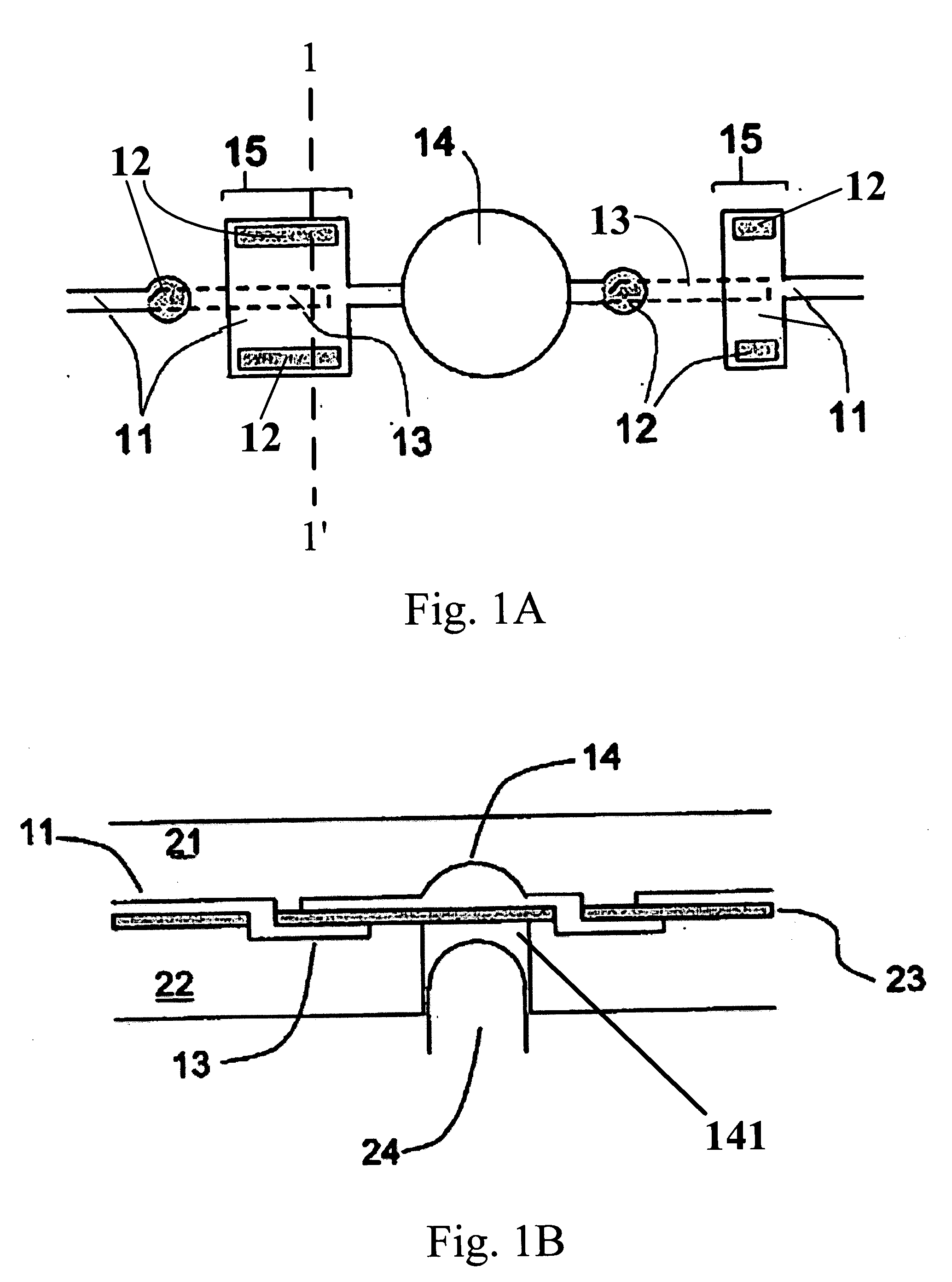
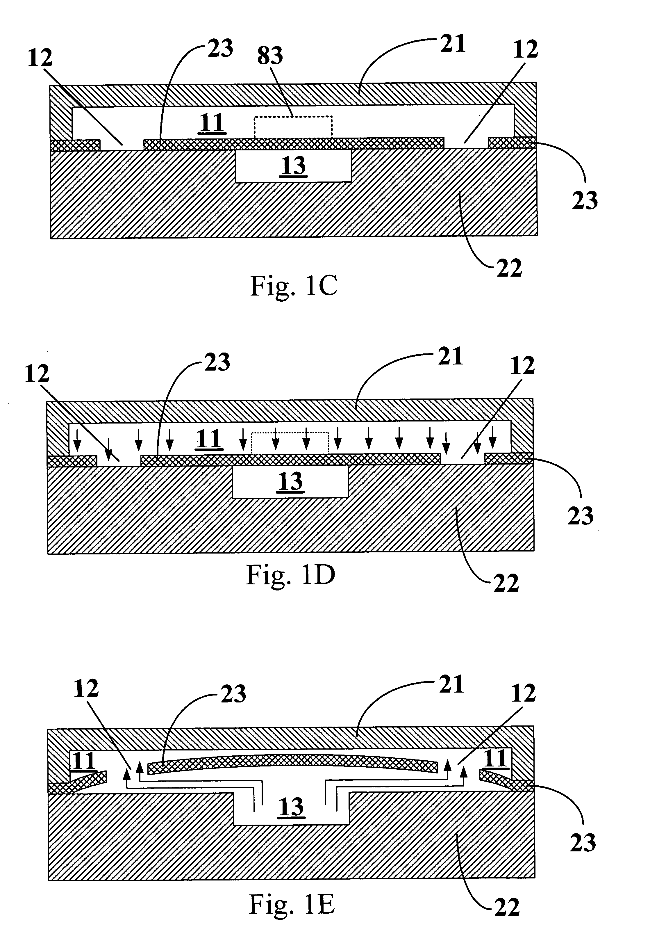
[0039] A system in accordance with one aspect of the invention comprises a plastic fluidic cartridge and a linear actuator system external to the fluidic cartridge. FIG. 1A shows a top view of a pump structure formed within the fluidic cartridge of the invention. The plastic fluidic cartridge is composed of three primary layers: an upper substrate 21, a lower substrate 22, and a flexible intermediate interlayer 23, as shown in FIG. 1B. The three layers can be assembled by various plastic assembly methods such as, for example, screw assembly, heat staking, ultrasonic bonding, clamping, or suitable reactive / adhesive bonding methods. The upper and lower substrates 21, 22 both contain a variety of features that define channels of capillary dimensions as well as pump chambers, valve chambers, reaction chambers, reservoirs, and inlet / outlet ports within the cartridge.

[0040]FIG. 1B shows a cross-sectional view of the pump structure of FIG. 1A. The pump is defined by a pump chamber 14 and ...


PUM


Abstract

An apparatus comprising a fluidic cartridge including a first and second substrate and an intermediate interlayer is provided. The intermediate interlayer is sealedly interfaced between the first and second substrates to form therein a plurality of channels of capillary dimensions. The apparatus further includes an open reservoir, a pump chamber and a reaction chamber. The open reservoir and reaction chamber are each connected to the pump chamber through the channels. The open reservoir and reaction chamber are in fluid communication with each other via the channels. The apparatus further comprises a fluid flow controlling structure, formed in the fluidic cartridge, which restricts a flow of a fluid through the reaction chamber to one direction. The apparatus further comprises a linear actuator for providing a pumping action in the pump chamber to pump the fluid to flow between the open reservoir and reaction chamber via the plurality of channels and pump chamber.

Description

CROSS REFERENCE TO RELATED APPLICATIONS [0001] This application is a continuation-in-part of U.S. patent application Ser. No. 10 / 437,046, filed May 14, 2003, which is incorporated by reference herein in its entirety. This application further claims priority, under 35 U.S.C. § 119, to Taiwanese patent application number 91122431, which was filed Sep. 27, 2002, and which is hereby incorporated by reference in its entirety.FIELD OF THE INVENTION [0002] This invention relates to systems comprising a fluid delivery and analysis cartridge and external linear actuators. More particularly, the invention relates to systems and methods for carrying out various processes, including screening, immunological diagnostics, DNA diagnostics, in a miniature fluid delivery and analysis cartridge. BACKGROUND OF THE INVENTION [0003] Recently, highly parallel processes have been developed for the analysis of biological substances such as, for example, proteins, peptides, nucleic acids (e.g., DNA, cDNA, e...

Claims


Application Information

Patent Timeline
IPC IPC(8): B01L3/00F04B43/02F04B43/04
CPCB01L3/50273Y10T436/2575B01L2200/10B01L2300/0816B01L2300/0861B01L2300/0867B01L2300/087B01L2300/0887B01L2400/0481B01L2400/0605B01L2400/0638F04B43/02F04B43/043F16K99/0001F16K99/0015F16K99/0034F16K99/0057F16K2099/0084F16K2099/0094B01L3/502738
Inventor WEBSTER, JAMES RUSSELLKUO, YUAN-FONGWANG, SHAW-TSUTAI, LUNG-WEN
Owner AST MANAGEMENT
Why Eureka
Try Eureka