Spray coating apparatus and spray coating method

a coating apparatus and spray technology, applied in the direction of superimposed coating process, liquid/solution decomposition chemical coating, manufacturing tools, etc., can solve the problems of affecting the coating pattern, affecting the coating quality, so as to reduce the amount of down flow, reduce the down flow speed, and reduce the adhesion efficiency

Inactive Publication Date: 2005-08-18
NIPPON PAINT CO LTD +1
View PDF11 Cites 29 Cited by
  • Summary
  • Abstract
  • Description
  • Claims
  • Application Information

AI Technical Summary

Benefits of technology

[0054] According to the present invention, since the coating is performed by controlling such that the air blown off from the first adapter and / or the second adapter is caused to substantially coincide with the induction flow rate generated due to the shaping, the gas quantity and the wind speed when the air arrives at the coated object become unchangeable from when the air blown off from each adapter is null, so that the coating pattern in the coated object face is not disturbed, and it is possible to obtain an optimum coating finish. However, the fact that the gas quantity and the wind speed when the air arrives at the coated object are made the same as a case where there is only the shaping air becomes the fact that the gas quantity and the wind speed of the air blown off from each adapter become zero in the coated object face. However, during a period before arriving at the coated object face, the air blown off from each adapter covers the periphery of the paint, and the temperature and the humidity are changed to and maintained at suitable conditions.
[0055] Here, “induction flow generated due to the shaping air” means a wind generated around the shaping air. Since the atomized paint particles moved by this wind are scarcely adhered to the coated object, the adhesion efficiency is reduced, and the coating machine main body and the like are contaminated by the paint particles blown back.
[0056] In the present invention, since the first adapter and / or the second adapter are / is provided, and since it is adapted such that the outer periphery of the coating pattern injected from the injection spray of the coating machine main body is covered by the twisted air and the outer periphery air (they are generically referred to as shield air) and the like supplied from the adapters, it is possible to reduce a down flow speed of the conventional coating booth, so that a down flow quantity reduces, a range of humidity adjustment at a coating time of aqueous paint becomes wide, and an energy used for the air conditioning is reduced as well. Further, by this shield effect, the scatter of the paint is prevented, the paint adhesion efficiency is increased, a use quantity of the paint can be reduced, and an industrial waste quantity is reduced as well.
[0057] Further, by adjusting the temperature, the humidity and the gas quantity of the shield air and the like, it becomes possible to control the adhesion viscosity of the atomized paint without air-conditioning the whole booth like the related art. Especially, in a case of the aqueous paint, when the coating is performed by a wet-on-wet coating, if the shield air whose temperature, humidity and the like have been adjusted at the coating time of a base paint is used, a time for flushing off (preheating) the coating film of the base paint after the coating can be shortened or nullified. Accordingly, the next coating of top clear paint can be started within a short time, and a flush-off process which has been necessary in the related art can be simplified.
[0058] Additionally, as to the first adapter, by forming in its inner wall face the air induction part capable of giving the predetermined blowoff angle, and by making it such that the air supplied from the first adapter shields, as the twisted air, the outer periphery of the coating pattern injected from the injection nozzle so as to cover the outer periphery, the coating can be performed while controlling the spread of the coating pattern near the injection nozzle, without disturbing the coating pattern.
[0059] Further, since the second adapter has the blowoff layers partitioned in many layers, and since it is adjusted in such a manner that the air blown off from the blowoff layer of the inner side among the many layers covers the outer periphery of the coating pattern near the coated object and that the air blown off from the blowoff layer of the outermost side prevents the diffusion of the air blown off from the blowoff layer of the inner side, the coating can be performed while controlling the spread of the coating pattern near the coated object without disturbing the coating pattern.

Problems solved by technology

However, in this method of the Patent Document 1, since the air (referred to as shield air) supplied to an outer periphery of the atomized paint particles pattern is supplied while being directed to substantially the same direction as moving directions of atomized paint particles to the coated object, it is impossible to prevent a turbulence of coating pattern.
Further, since this method supplies the air to the external electrode, it is unavoidable that the paint adhesion efficiency reduces because an induction flow occurs excessively to a bell part.
However, in this method of the Patent Document 2, since the shield air of large gas quantity impinges against the compressed air (shaping air), the shield air is disturbed and eventually the coating pattern is disturbed as well.
Further, in this method, since a blowoff directs to an axial direction, the pattern is disturbed and thus the paint adhesion efficiency is reduced.
In order that it is not disturbed, there arises a problem that a heat quantity cannot be supplied sufficiently.
However, in this method of the Patent Document 3, since the air (referred to as shield air) widely blown from an air blowing device impinges against the coating pattern of the atomized paint flow blown from the atomization device to the coated object, the coating pattern is disturbed unless such a contrivance that a wind of an inside is made weak and a wind of an outside strong is performed, so that an adjustment of the shield air is difficult.
However, since a quantity and a bowoff angle of the supplied air cannot cope with an atomization angle change of the atomized spray paint particles, the pattern of the coating is disturbed and a problem occurs in the coating itself, so that such attempts were not put to practical use.

Method used


Image

  • Spray coating apparatus and spray coating method
  • Spray coating apparatus and spray coating method
  • Spray coating apparatus and spray coating method

Examples


examples

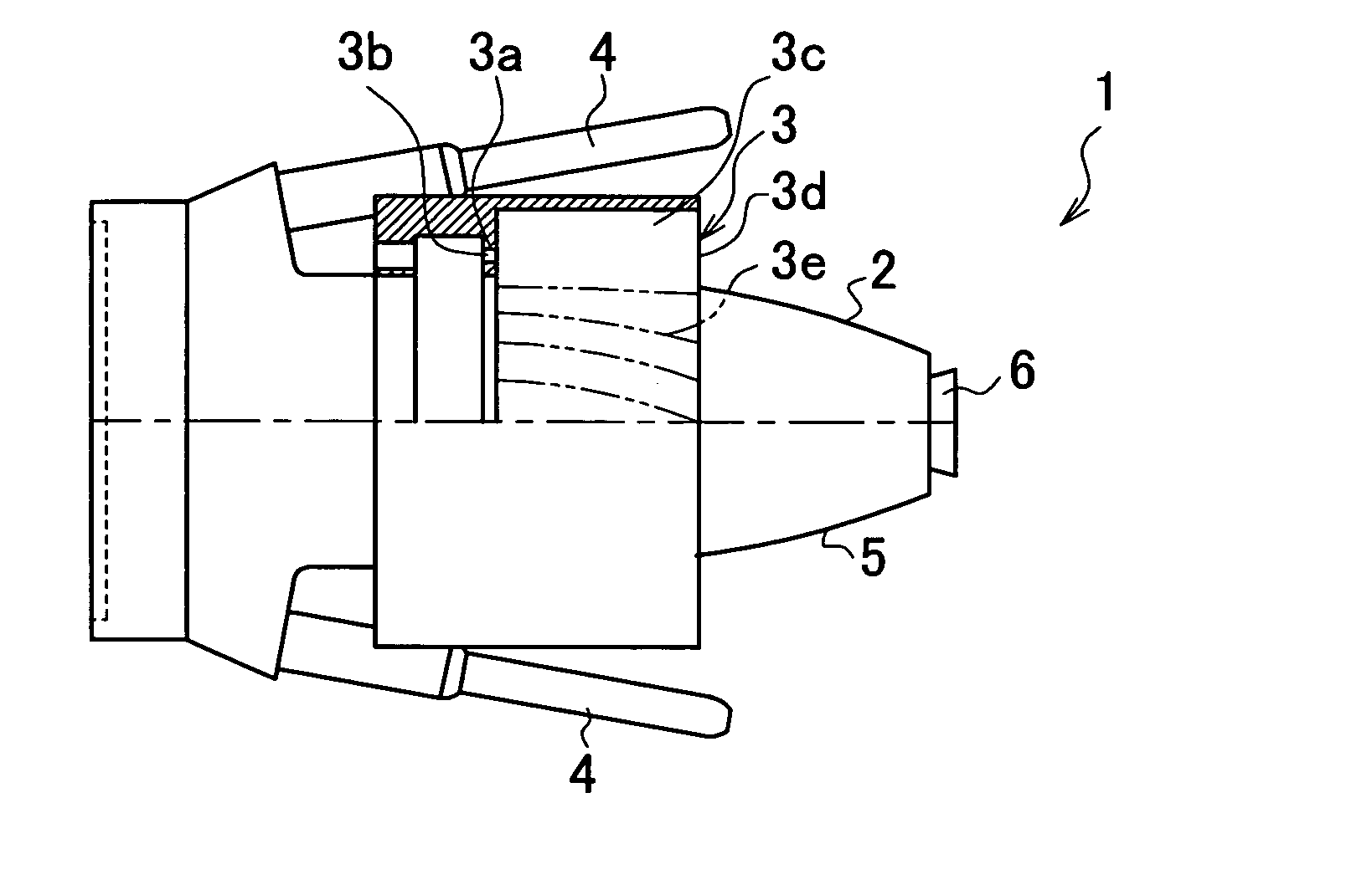
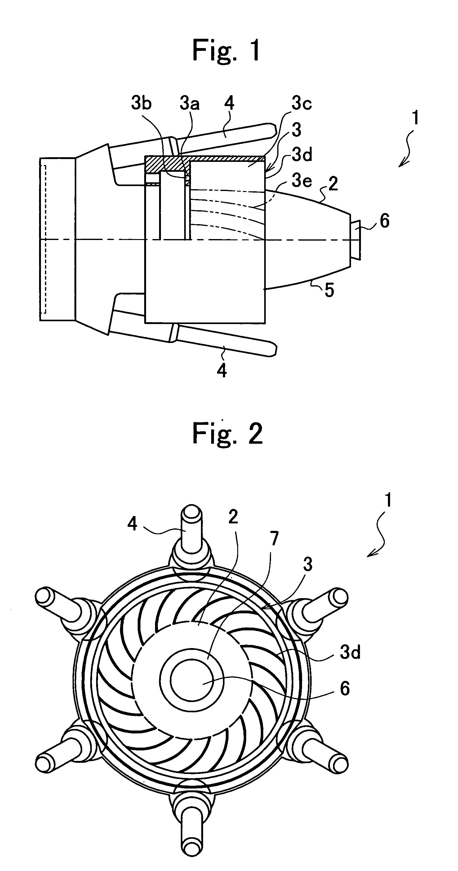
[0159] Test results of the coating method of the present invention are shown below. In the present example, the spray coating apparatus 1 of the present invention shown in FIG. 1 was used, an aqueous base paint of solid component 20 weight % was coated on a vertically provided tinplate sheet of about 0.3 mm in thickness, and a coated sheet was obtained. However, a spacing between the injection nozzle and the coated object was made 220 mm.

[0160] As to coating conditions of the aqueous base paint, the number of revolution was made 50000 rpm, a paint discharge quantity 270 cc / min, a shaping air pressure 300 Nl / min, and an applied current 400 μA. Temperatures of the temperature-controlled shield air were the room temperature, 50° C. and 77° C. (humidity 70% RH in all temperatures), and the air whose supply quantity had been set to 2 m3 / min was blown off from the first adapter. However, the angle of the twisted air blown off from the first adapter was made 30°.

[0161] There was measured...


PUM

PropertyMeasurementUnit
voltageaaaaaaaaaa
twisted angleaaaaaaaaaa
temperatureaaaaaaaaaa

Abstract

By forming an air flow in which a quantity and a blowoff angle of the air supplied toward an atomized spray paint flow don't influence a coating pattern, there are provided a coating apparatus and a coating method, each of which does not disturb the coating pattern, does not require conditions such as wind speed and temperature of a conventional coating booth, and can perform remarkable reduction in an air conditioning energy of the coating booth, prevention of scatter of a paint, and an improvement in a paint adhesion efficiency. In a spray coating apparatus which possesses a casing and an injection nozzle provided in a tip side of the casing and which forms a coating pattern by injecting paint and shaping air from the injection nozzle to thereby form a coating film on a coated object, a first adapter which blows off the air in an injection direction of the injection nozzle is provided on an substantially concentric circle of the injection nozzle, and the first adapter covers, by blowing off the introduced air while giving it a blowoff angle slanting toward a circumferential direction, an outer periphery of the coating pattern near the injection nozzle with the air.

Description

CROSS-REFERENCE TO RELATED APPLICATIONS [0001] This application is based upon and claims the benefit of priority from the prior Japanese Patent Application No.2003-372645 filed on Oct. 31 in 2003, the entire contents of which is incorporated herein by reference. FIELD OF THE INVENTION [0002] The present invention relates to an atomized spray coating apparatus and a coating method, which are used in an automobile coating and a building exterior coating and, especially, are for to a remarkable reduction in air conditioning energy, paint scatter prevention and an improvement in paint adhesion rate in a spray coating. BACKGROUND OF THE INVENTION [0003] Conventionally, there have been attempted to prevent a paint from scattering by forming an air flow which deflects paint particles atomized by an injection spray to a coated object direction, and to relieve a booth room air conditioning by performing the air conditioning by adjusting a temperature, humidity and the like of the supplied ai...

Claims


Application Information

Patent Timeline
Patent Type & Authority Applications(United States)
IPC IPC(8): B05D1/04B05B1/28B05B1/34B05B5/04B05B5/053B05B7/06B05B7/08B05B7/16B05B12/10B05B15/12
CPCB05B5/001B05B5/0407B05B5/0426B05B15/12B05B7/0815B05B7/16B05B12/10B05B5/0533B05B16/00
Inventor HIRANO, KATSUMITAKESHITA, KATSUHIROKANAKURA, AKIHIROYAMASAKI, SATOSHI
Owner NIPPON PAINT CO LTD
Why Eureka
Try Eureka