

Metal-cladded metal matrix composite wire
a metal-clad metal and composite wire technology, applied in the direction of magnetic materials, magnetic bodies, transportation and packaging, etc., can solve the problems that conventional metal-clad composite wires are difficult to process to high levels of dimensional tolerance, and achieve the effect of preventing secondary fractures and reducing recoil effects
- Summary
- Abstract
- Description
- Claims
- Application Information
AI Technical Summary
Benefits of technology
Problems solved by technology
Method used
Image

Examples
example 1
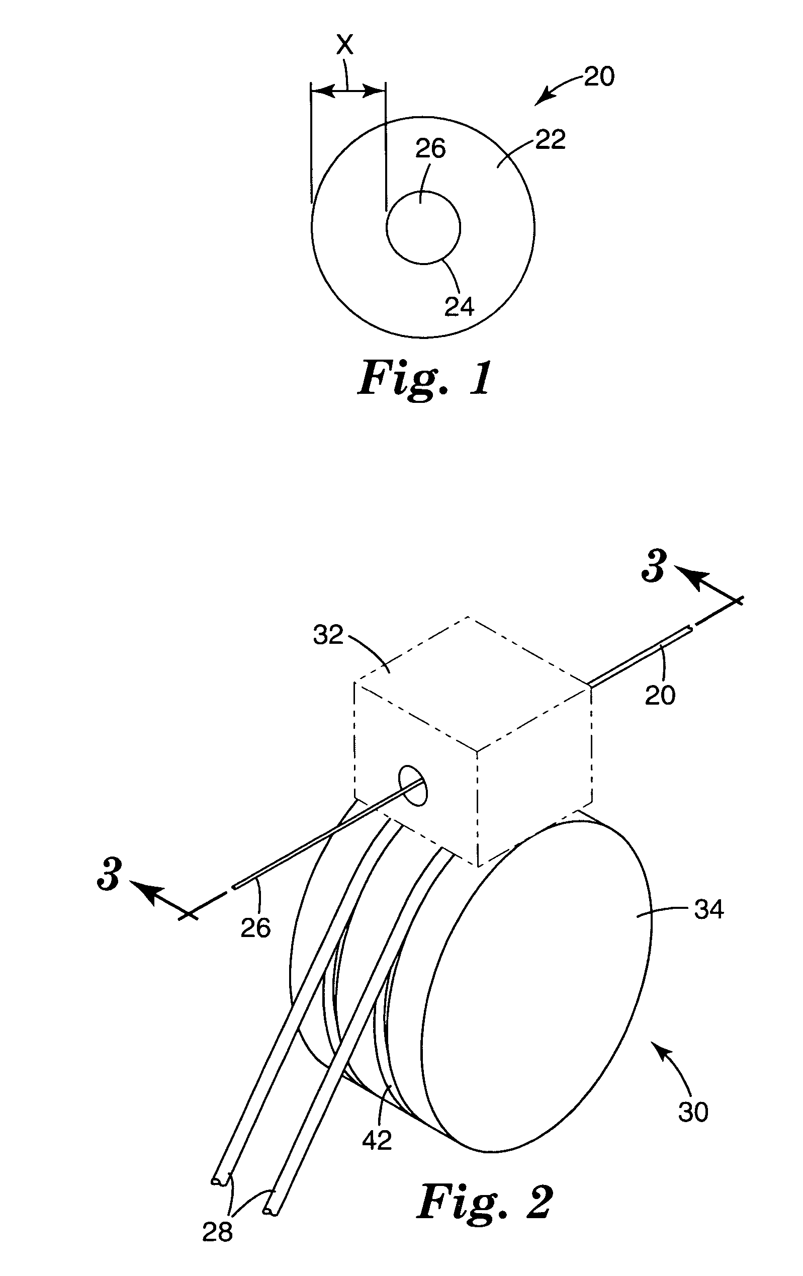
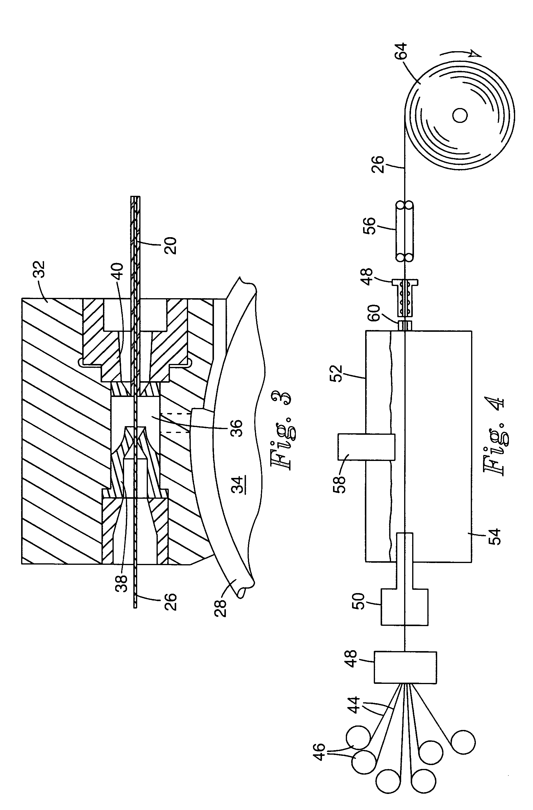
[0102] An aluminum matrix composite wire was prepared using 34 tows of 1500 denier “NEXTEL 610” alumina ceramic fibers. Each tow contained approximately 420 fibers. The fibers were substantially round in cross-section and had diameters ranging from approximately 11-13 micrometers on average. The average tensile strength of the fibers (measured as described above) ranged from 2.76-3.58 GPa (400-520 ksi). Individual fibers had strengths ranging from 2.06-4.82 GPa (300-700 ksi). The fibers (in the form of multiple tows) were fed through the surface of the melt into a molten bath of aluminum, passed in a horizontal plane under 2 graphite roller, and then back out of the melt at 45 degrees through the surface of the melt, where a die body was positioned, and then onto a take-up spool (e.g. as described in U.S. Pat. No. 6,336,495 ((McCullough et al.), FIG. 1). The aluminum (>99.95% Aluminum from Belmont Metals, NY, N.Y.) was melted in an alumina crucible having dimensions of 24.1 cm×31.3 ...
example 2
[0120] Example 2 was prepared as described in Example 1 with the exception that the core wire 26 was heated using induction heating to 300° C. (surface core temperature) prior to inserting in inlet guide die 38. This resulted in a clad wire (MCCW 20) of 304 m (1000 ft) length and 0.70 mm (0.03 inch) cladding wall thickness.
[0121] Using the wire tensile Strength test described above, clad wire (MCCW 20) made in Example 2 was tested. 63.5 cm ((25 inch gauge length)).
MCCW 20 of Example 2ACW 26 of Example 2Load = 4888 ± 107 NLoad = 4066 ± 147 N(1099 ± 24 lbs)(914 ± 33 lbs)(COV = 2.2%)(COV = 3.6%)Strain = 0.78 ± 0.03%Strain = 0.66 ± 0.05%Modulus = 108 GPaModulus = 223 GPa(15.6 ± 1.8 Msi)(32.3 ± 1.5 Msi)Strength = 499 MPa (72.4 ± 1.6 ksi)Strength = 1220 MPa (177 ± 6 ksi)10 tests10 tests
[0122] Clad wire (MCCW 20) from Example 2, was analyzed to determine the yield strength of the aluminum cladding. A graph of stress-strain behavior for the clad wire of Example 2 is illustrated in FIG. 9...
example 3
[0124] AMC core wires 26, 2.06 mm (0.081 inch) diameter cladded with a 0.7 mm (0.03 inch) aluminum cladding 22 (as described for Example 1), were tested to failure in tension. The clad wire (MCCW 20) had a 635 mm (25 inch) gage length. The clad wire did not exhibit secondary fractures after primary failure in tension (the load to failure was on average 4900 N). The absence of secondary fractures was verified by re-gripping the longer section of broken wires (MCCW 20) and re-testing them in tension (the gage length was still greater than 38.1 cm (15 inch). Upon re-testing, the clad wires (MCCW 20) exhibited a slightly greater load to failure (˜5000N). This result indicated that there were no hidden secondary fracture sites in the clad wire. The load-displacement also clearly indicated the role of the aluminum cladding 22 when the primary tensile failures occur, as shown in the graph of FIG. 10. The sudden drop in load is associated with the primary failure on the ACW 26, however, the...
PUM
| Property | Measurement | Unit |
|---|---|---|
| melting point | aaaaa | aaaaa |
| diameter | aaaaa | aaaaa |
| melting point | aaaaa | aaaaa |
Abstract
Description
Claims
Application Information