
Sampling and assay device together with methods for use thereof

Inactive Publication Date: 2005-08-18
ANI BIOTECH
View PDF24 Cites 9 Cited by
  • Summary
  • Abstract
  • Description
  • Claims
  • Application Information

AI Technical Summary

Benefits of technology

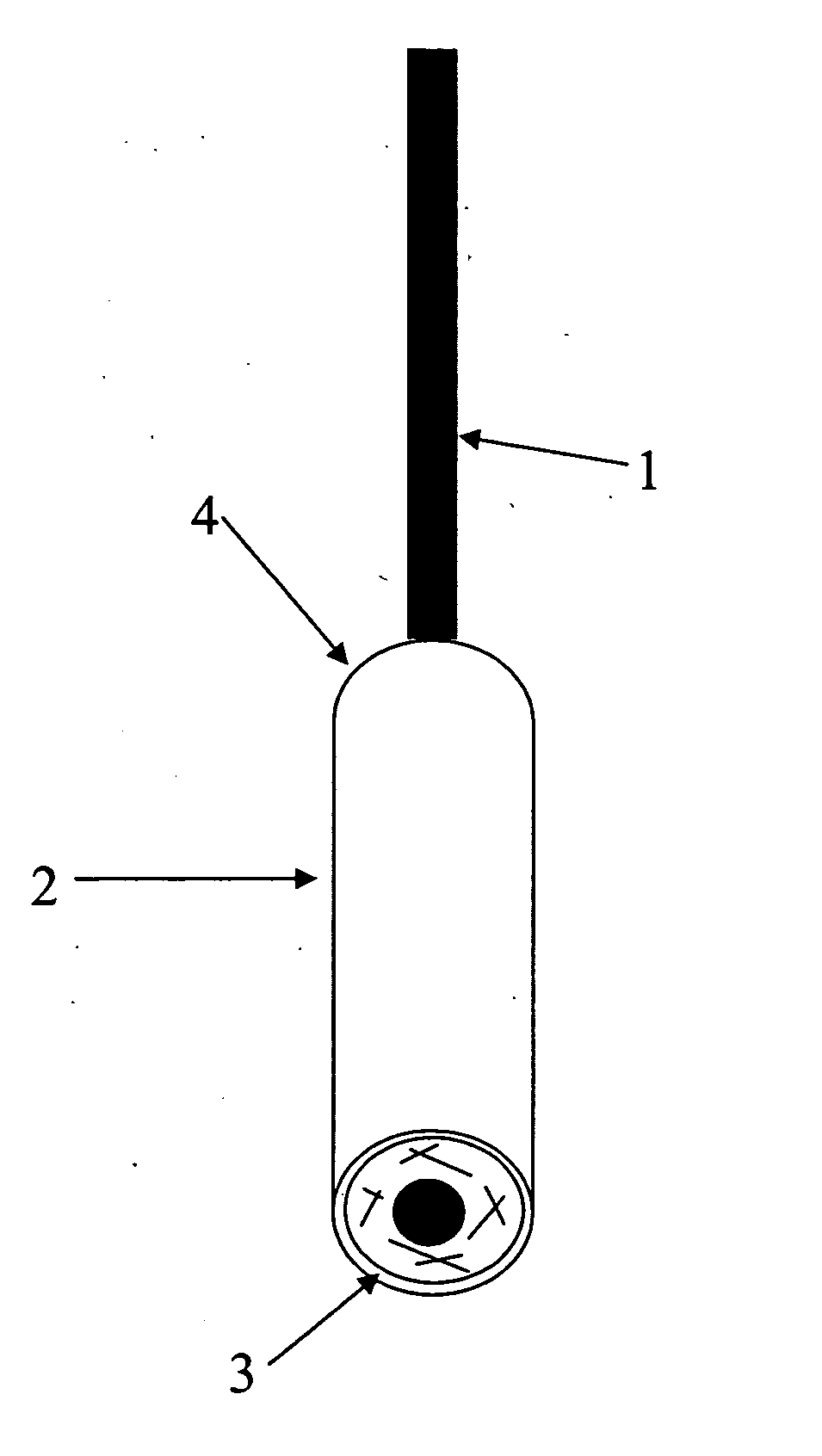
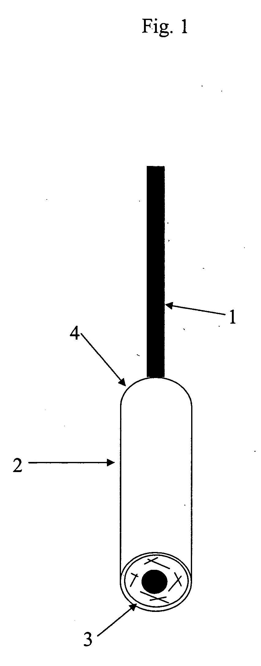
[0016] In use, the wrapped portion of the sampling device is brought into contact with a fluid sample (e.g., by immersion or introduction into a stream of sample) so sample contacts the proximal edge of the porous carrier, which proximal edge is exposed beneath the hydrophobic cover. The porous carrier is wrapped around the solid support (which serves at its unwrapped end as a handle) in a manner designed to optimize flow of sample into the porous carrier, as well as flow of sample mixed with labeled binding reagent out of the porous carrier on contact with an analyzer device. The volume and rate of flow of sample through the porous carrier are controlled as well by pressure equilibrization means provided in the hydrophobic cover.
[0018] Preferably, the analyzer device comprises a test strip on which a binding reagent is immobilized within a test zone downstream of a sample application site at which no binding reagent need be bound. Most preferably, the analyzer device further comprises a solid housing for the test strip having a depression into which the sample application site of the test strip is deflected under gentle pressure applied to the sampling device, to facilitate flow of sample out of the porous carrier.
[0020] The test system is easy to use, and may therefore be provided for at home use. Because sample fluid is not applied directly to the analyzer device, saturation of the test strip and / or contamination of the test zone are avoided. In short, the invention provides a device for collecting and testing sample fluids for the presence of analytes that is uniquely simple to use and manufacture.

Problems solved by technology

In use, the sample solution is applied directly to the test device when the test is performed, which exposes the test zone to risk of overflow.
However, when a single component is used both to collect and test a fluid sample there is a risk that the sensitive reagents and the structure of the analytical device is will be contaminated or otherwise disturbed.

Method used


Image

  • Sampling and assay device together with methods for use thereof
  • Sampling and assay device together with methods for use thereof
  • Sampling and assay device together with methods for use thereof

Examples


example 1

Pregnancy Test Construction

[0049] Example 1 relates to a hCG pregnancy test, in which a protecting impermeable layer is added to the sampling device in order to attach and protect the porous carrier containing the specific labeled reagent. A control zone is added to ensure a proper performance of the test. Components utilized in the device were as follows:

ComponentRaw materialSpecificationsLabeled anti-In vitro produced,0.9% NaCl;hCG antibodyaffinity purified0.1% NaN3 asIgGpreservativeTest line:In vitro produced,Phosphate-citrateanti-hCG antibodyaffinity purifiedbuffer; NaN3 asIgGpreservativeIndependent1.1.control system:keyhole limpetCopper-containingLabeledhemocyaninprotein with an1. keyhole limpetprotein ORoxygen-carryinghemocyanin OR2.function2. anti-leguminin vitro produced,2. In PBS bufferIgGaffinity purifiedpH 7.4 withIgG0.1% NaN3 aspreservativeControl line:In vitro produced,In sodium phosphateanti-keyholeaffinity purifiedbuffer with 0.1%limpet hemocyaninantibodiesNaN3 as(...

example 2

Pregnancy Test

[0055] Example 2 relates to a hCG-pregnancy test where the porous carrier containing the specific labeled reagent is attached without a impermeable layer. A control zone is added to ensure a proper performance of the test.

[0056] A polyester filter was pretreated as described in Example 1. One layer of the filter was adhered with an adhesive around a solid stick of wood, and covered with a tape forming a protective layer formed as described in Example 1. The analyzer device was made as in Example 1 and finally the devices were dried and packed as described in Example 1.

[0057] The test was performed by immersing the sampling device for 10 seconds in a liquid sample containing hCG. The stick was shaken lightly and thereafter placed in the sample well of the analyzer device. The presence of hCG was detected as described in Example 1.

example 3

Fertility Test Detection System

[0058] Example 3 describes how the invention can be applied for a fertility test detection system.

[0059] 3 μl / cm of a gold conjugate solution which comprised three labeled specific antibodies for hCG, LH and FSH was applied to a cellulose filter. The solution was added to a 3 mm wide area at one edge of the material using tube pumps and was then dried. The cellulose filter was blocked with a blocking solution comprising BSA (0.1-1.0%), Tween 20 (0.01-0.05%) and trehalose (0.5-1.5%).

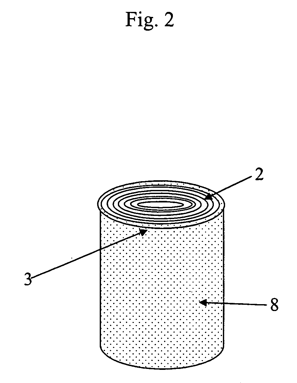
[0060] The cellulose filter was cut in 25 mm×27 mm pieces. One piece of the cellulose filter was rolled as four layers around a round hollow stick made of polypropylene and attached with a tape. The edge with the impregnated binding reagent was set in the lower end of the sampling device.

[0061] The analyzer device of FIG. 5 was constructed by blocking a porous carrier of nitrocellulose with a blocking solution comprising BSA (0.1-1.0%), Tween 20 (0.01-0.05%) and trehalos...


PUM


Abstract

An immunochemical sampling device, kits including the sampling device, processes for production of the sampling device, and methods for use of the sampling device in lateral flow immunoassays. The sampling device comprises a solid support that is partially wrapped in a porous carrier, then covered in a hydrophobic cover. At its distal end, the porous carrier comprises a labeled binding reagent that is retained in the solid support until released into controlled flow with the liquid sample when the sampling device is brought into contact with a test strip.

Description

CROSS-REFERENCE TO RELATED PATENT APPLICATIONS [0001] This application claims the benefit of the priority of European Patent Application No. 04003603.0, filed on Feb. 18, 2004. BACKGROUND OF THE INVENTION [0002] The present invention relates to an immunochemical sampling device, especially to devices for conducting immunoassays that are suitable for home use, at doctors' offices and / or by technically untrained staff, involving a minimal level of skill from the users. [0003] Methods and devices based on immunodiffusion are known from for example U.S. Pat. Nos. 4,757,002, 3,990,852 and 4,562,147. Immunochromatographic methods based on lateral flow are known from EP 0 291 194; EP 0 284 232; EP 0 250 137; U.S. Pat. Nos. 5,250,412; 5,084,245; 5,760,315; 6,375,896 and WO 86 / 03839. [0004] U.S. Pat. No. 4,562,147 provides a radial immunodiffusion enzyme assay method for testing of pseudorabies antibodies in swine and other animals. Agar test plates are provided including an underlying adher...

Claims


Application Information

Patent Timeline
IPC IPC(8): B01L3/00C12M1/30G01N33/543G01N33/558
CPCG01N33/558B01L3/5029G01N2001/028
Inventor NISKANEN, AIMOSARAMAKI, MIKA
Owner ANI BIOTECH
Learn More