Gas-phase process

Inactive Publication Date: 2005-08-18
UNIVATION TECH LLC
View PDF9 Cites 67 Cited by
  • Summary
  • Abstract
  • Description
  • Claims
  • Application Information

AI Technical Summary

Benefits of technology

[0009] There is disclosed a continuous gas fluidized bed polymerization process for the production of a polymer from a monomer including continuously passing a gaseous stream comprising the monomer through a fluidized bed reactor in the presence of a catalyst under reactive conditions; withdrawing a polymeric product and a stream comprising unreacted monomer gases; cooling said stream comprising unreacted monomer gases to form a mixture comprising a

Problems solved by technology

The primary limitation on increasing the reaction rate in a fluidized bed reactor is the rate at which heat can be removed from the polymerization zone.
The fluid velocity in the reactor is limited to prevent excessive entrainment and carry-over of solids.
This assumption was predicated on the belief that the introduction of liquid into a gas phase fluidized bed reactor would inevitably result in plugging of the distribution plate, if one is employed, less-than-adequate fluidization inside the reactor and accumulation of liquid at the bottom of the reactor which would interfere with continuous operation or result in complete reactor shut-down.
For products, such as those using hexene as a comonomer, the relatively high dew point of the recycle stream has severely restricted the production rate.
Currently used ICA's, such as pentane, facilitate heat removal from the reactor, but with production rate constraints as described above.
Specifically, increasing the amounts of these ICAs generally causes the produced polymer to reach the stickiness limit.
Once the polymer is at or above the stickiness limit, small polymer pieces stick to each other and may clog the reactor.

Method used


Image

  • Gas-phase process
  • Gas-phase process

Examples


examples

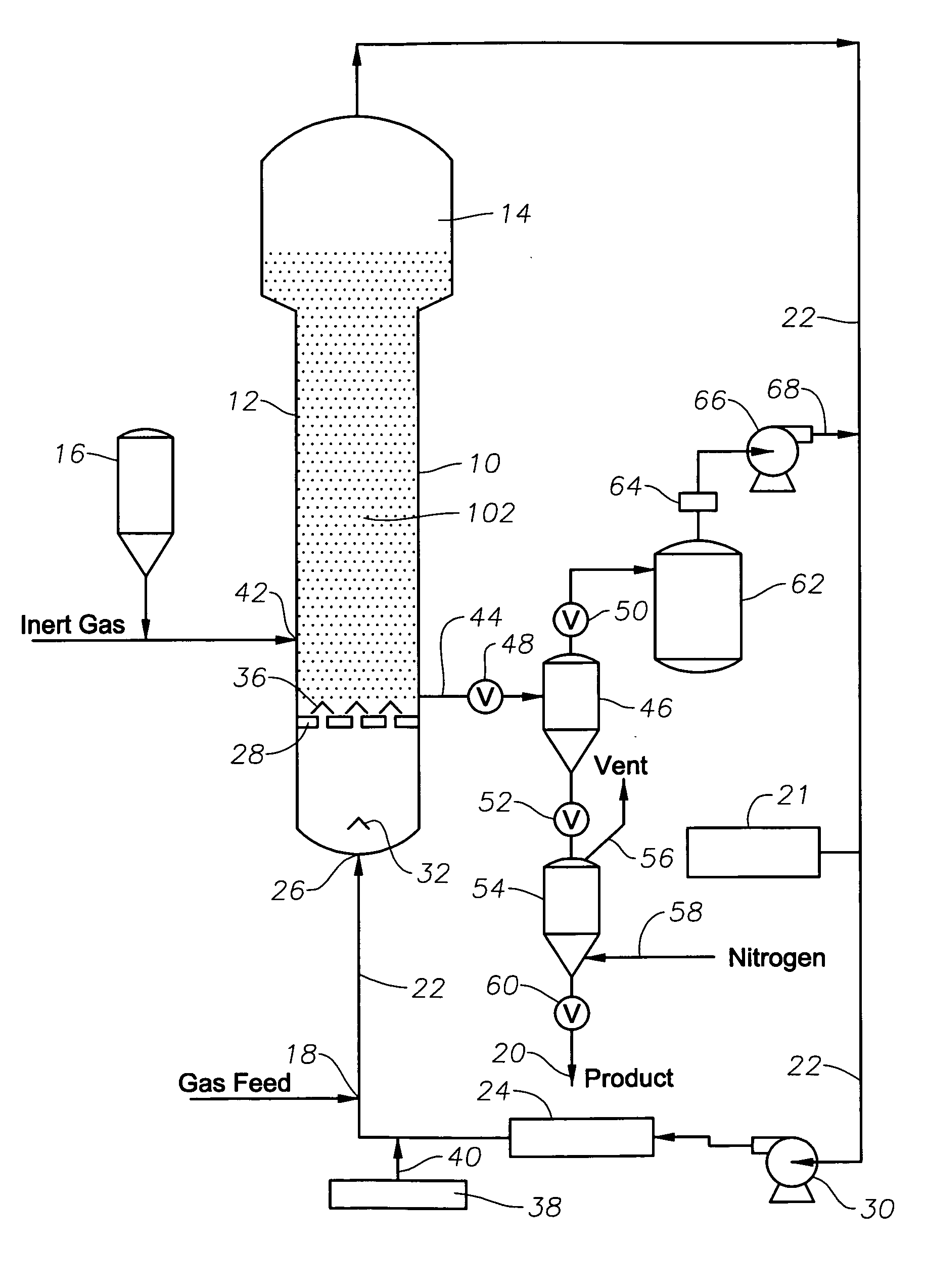
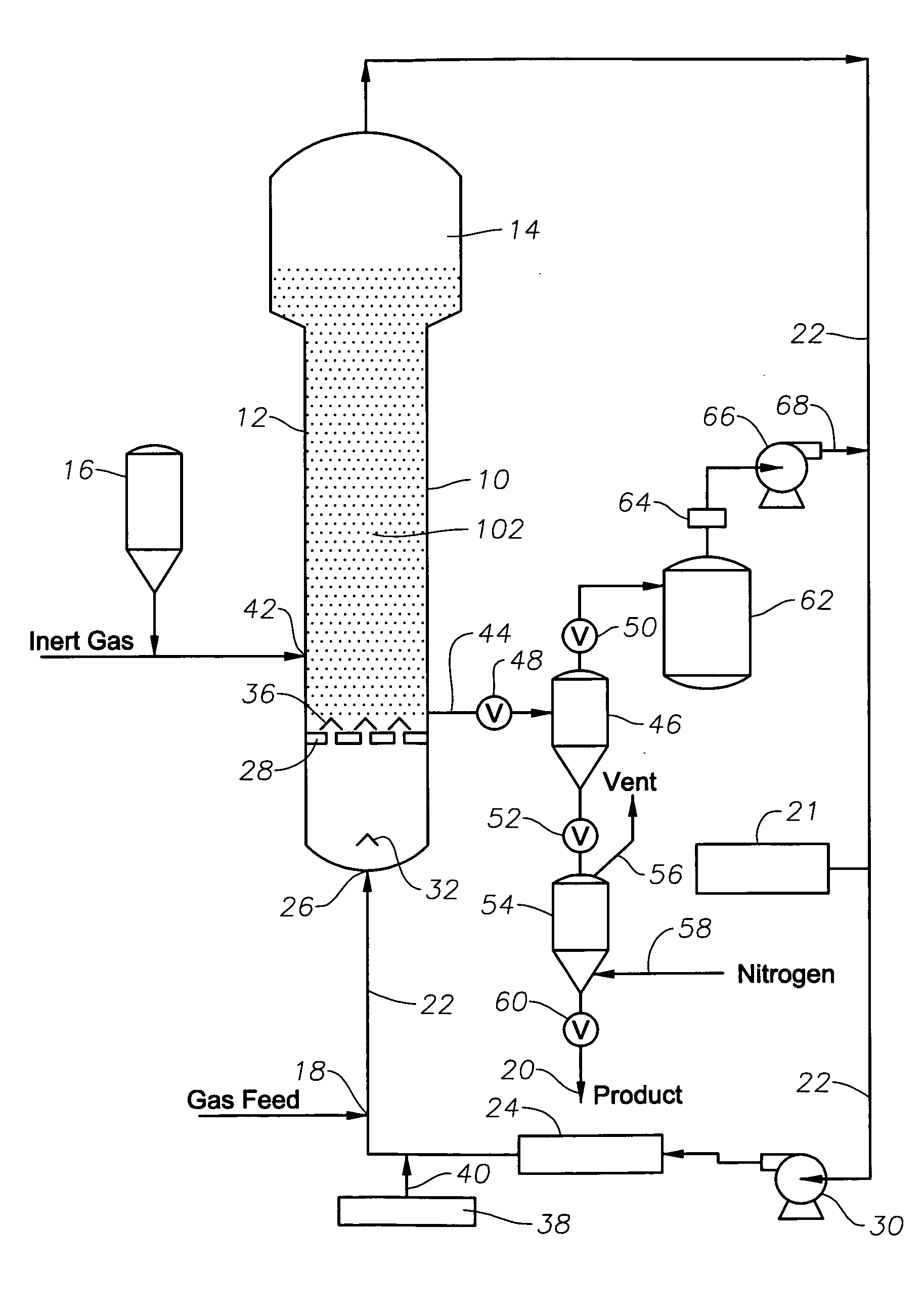
[0080] All the following examples are related to commercial scale operations conducted in a gas phase fluidized bed polymerization reactor similar to the one as shown and described above in FIG. 1. Detailed operating conditions and operation results of these examples are listed in Table 2.

[0081] Examples 1 employs low amounts of ICAs. Example 2 employs relatively larger amounts of ICAs. It can be seen from Table 2 that a significant increase of production rate is achieved by Example 2 as compared to Example 1.

TABLE 2Example12ProductPEPEComonomerButeneButeneCatalystZiegler-NattaMetalloceneResin Density (g / cc)0.9190.919Melt index (dg / min) *2.02.0Inert Condensing AgentsPentanes & butanesPentanes & butanesReactor Pressure (psig)350?350?Reactor Temperature (° C.)85.485.4Gas composition (mol %)??Ethylene38.436.6Butene15.014.8Hydrogen10.19.7Ethane2.12.8N-pentane4.13.3N-butane2.46.2Iso-petane5.55.5Iso-butane0.10.5Total Butanes2.56.7Nitrogen22.220.5Superficial Gas Velocity0.810.82(m / s)Dew...


PUM

PropertyMeasurementUnit
Temperatureaaaaaaaaaa
Weightaaaaaaaaaa

Abstract

A continuous gas fluidized bed polymerization process for the production of a polymer from a monomer including continuously passing a gaseous stream comprising the monomer through a fluidized bed reactor in the presence of a catalyst under reactive conditions; withdrawing a polymeric product and a stream comprising unreacted monomer gases; cooling said stream comprising unreacted monomer gases to form a mixture comprising a gas phase and a liquid phase and reintroducing said mixture into said reactor with sufficient additional monomer to replace that monomer polymerized and withdrawn as the product, wherein said liquid phase is vaporized, and wherein the stream comprises at least two inert condensing agents selected from the group consisting of alkanes, cycloalkanes, and mixtures thereof, each of the inert condensing agents having a normal boiling point less than 40° C.

Description

CROSS-REFERENCE TO RELATED APPLICATION [0001] The present application claims priority to provisional U.S. Ser. No. 60 / 532,057 filed Dec. 23, 2003.FIELD OF THE INVENTION [0002] The present embodiments relate to processes for condensing mode operation of a gas-phase polymerization reactor. More specifically, the present embodiments are directed to the use of multiple low boiling point inert condensing agents, or multiple inert condensing agents having low solubilities in a polymer, which allow the introduction of more inert condensing agents into the reactor to promote more heat removal than a conventional inert condensing agent. BACKGROUND OF THE INVENTION [0003] The condensing mode of operation in gas-phase polymerization reactors significantly increases the production rate or space time yield by providing extra heat-removal capacity through the evaporation of condensates in the cycle gas. Additional condensation is often promoted to extend the utility of condensed mode operation by...

Claims


Application Information

Patent Timeline
IPC IPC(8): C08F2/00C08F10/02C08F210/16
CPCC08F10/02C08F210/16C08F2/34C08F210/14C08F2500/12
Inventor SINGH, DIWAKERHINDS, SANDY C.FISCHBUCH, BRETTAI VEY, NG
Owner UNIVATION TECH LLC
Why Eureka
Try Eureka