
Disk array apparatus and disk array apparatus control method

a technology of disk array and control method, which is applied in the direction of instruments, input/output to record carriers, memory adressing/allocation/relocation, etc., can solve the problems of long halt time of the system, illegal data written into the database, software fault, etc., and achieve the effect of reducing the storage capacity required and quickly restoring the database without lowering the performance of external access

Inactive Publication Date: 2005-08-18
HITACHI LTD
View PDF13 Cites 43 Cited by
  • Summary
  • Abstract
  • Description
  • Claims
  • Application Information

AI Technical Summary

Benefits of technology

[0012] It is a main object of the present invention to provide a disk array apparatus and a disk array apparatus control method capable of reducing the storage capacity required to back up the database against a hardware fault or a software fault, quickly restoring the database without lowering the performance of external access to the database, and acquiring a backup at a certain point in time to provide against an emergency, without stopping the database update processing.

Problems solved by technology

Besides the hardware faults, in the database operation, illegal data is written into the database in some cases because of malfunction in software, a user's operation mistake, or the like.
Such a fault is called software fault.
Since a considerably long time is required to restore data from the magnetic tape or the like, the halt time of the system becomes long.
When a software fault has occurred, therefore, it is demanded to recover the database quickly by using data in the disk array apparatus without restoring data from the external storage medium such as magnetic tape.
In the case where the above-described two replica volumes are used, a storage capacity which is three times that of the volume storing the database becomes necessary, and the cost required to introduce a disk array apparatus increases.
This results in a problem that the performance of external access to the database is degraded during the resynchronization processing.

Method used


Image

  • Disk array apparatus and disk array apparatus control method
  • Disk array apparatus and disk array apparatus control method
  • Disk array apparatus and disk array apparatus control method

Examples


Embodiment Construction

==Disk Array Apparatus==

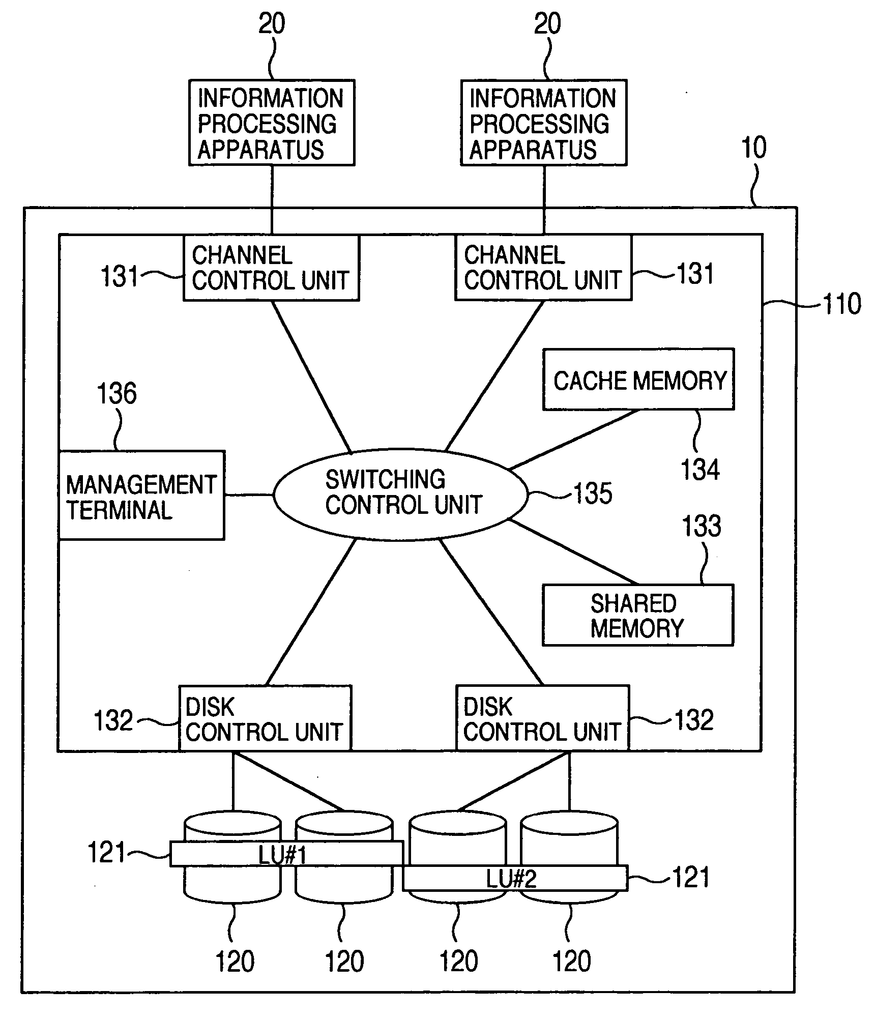
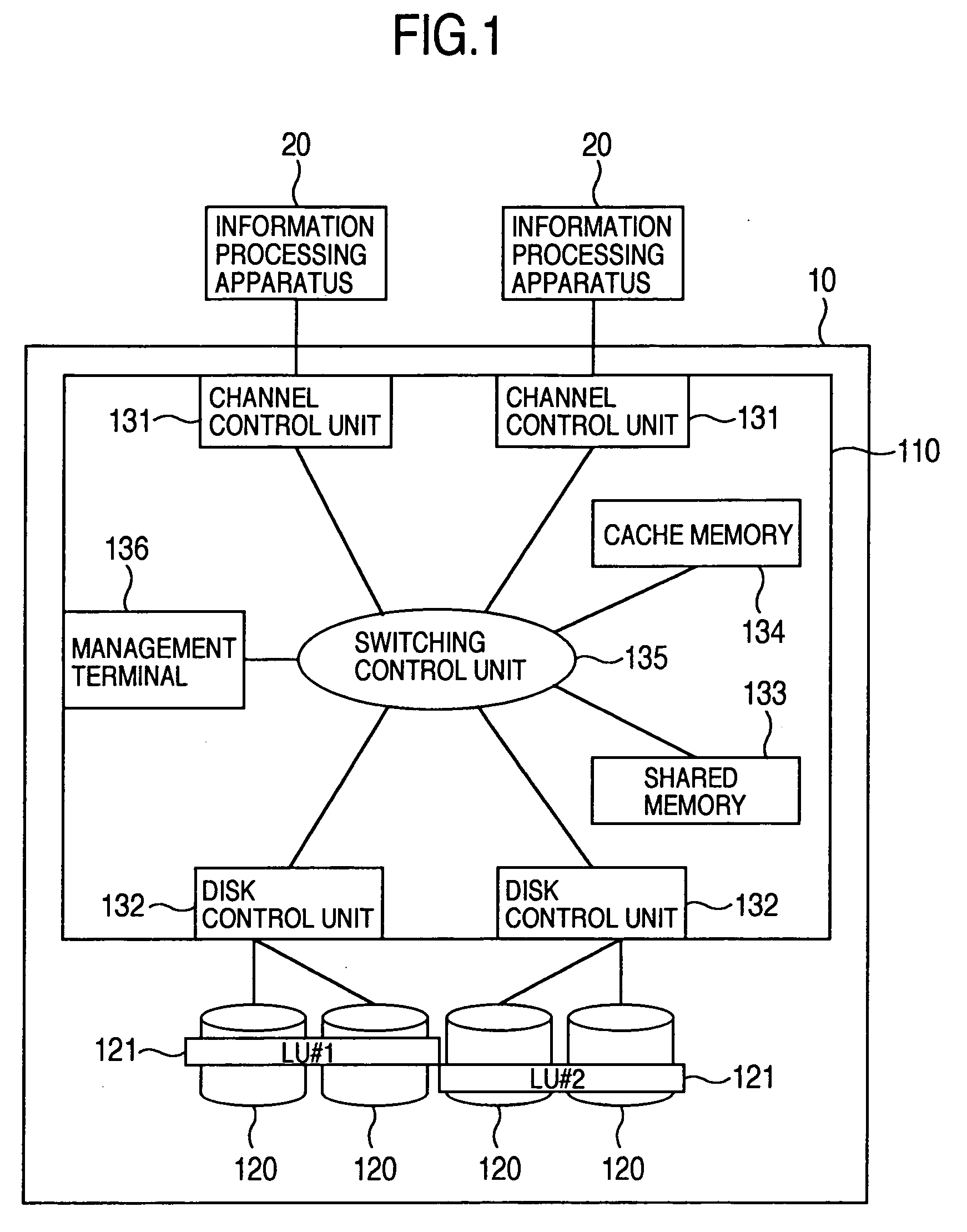
[0039] A first form of a disk array apparatus according to an embodiment is shown in FIG. 1. The disk array apparatus 10 includes a disk control device 110 and a plurality of hard disk drives 120. The disk array apparatus 10 is connected to information processing apparatuses 20 via communication means. The communication means is, for example, a LAN (Local Area Network), a SAN (Storage Area Network), an iSCSI (Internet Small Computer System Interface), an ESCON (Enterprise Systems Connection) (registered trademark), and a FICON (Fibre Connection) (registered trademark).

[0040] The information processing apparatus 20 is a computer including a CPU (Central Processing Unit) and a memory. The information processing apparatus 20 is a computer such as a personal computer, a work station, or a main frame. The information processing apparatus 20 is formed of a plurality of linked computers in some cases. In the information processing apparatus 20, an operating system...


PUM


Abstract

A journal write unit writes journal data into a third storage device. The journal data includes an identifier of a logical volume in a first storage device into which data has been written, information of a location in which the data is stored in the logical volume, update time which is current time acquired from a timing mechanism, and the data. A second write unit refers to update time of the journal data stored in the third storage device, selects journal data for which a difference between current time acquired from the timing mechanism and the update time is longer than a detection time stored in the third storage device, and writes the data into a place indicated by the location information, in a logical volume in the second storage device in the order of update time in the selected journal data.

Description

CROSS-REFERENCE TO RELATED APPLICATION [0001] The present application relates to and claims priority from Japanese Patent Application No. 2004-038169 filed on Feb. 16, 2004, the entire contents of which is incorporated herein by reference. BACKGROUND OF THE INVENTION [0002] The present invention relates to a disk array apparatus and a disk array apparatus control method. [0003] In recent years, information processing systems operated for 24 hours without halt, such as commodity sale systems using the Internet, have increased. Data used in such an information processing system are often stored in a database on a disk array apparatus as the data quantity increases and improvement of fault tolerance is requested. In information processing systems operated without halt, it is necessary to back up data stored in the database without stopping database update processing. Therefore, a method of providing a replica volume for backup in a disk array apparatus and storing data stored in the da...

Claims


Application Information

Patent Timeline
IPC IPC(8): G06F3/06G06F11/14G06F12/00G06F17/30
CPCG06F11/1456G06F11/1461G06F11/1469G06F11/1451G06F11/1471G06F2201/80
Inventor MUROTANI, AKIRAISHIKAWA, ATSUSHIKISHIMOTO, TETSUYA
Owner HITACHI LTD
Learn More