Hydraulic lash adjuster

a technology of lash adjuster and lash plate, which is applied in the direction of valve arrangement, basic electric elements, semiconductor devices, etc., can solve the problems of inhibiting the free movement of the valve element and the wear of the valve seat face, and achieve the reduction of the inertial mass of the valve element in a collision with the valve seat face. , the effect of small specific gravity

Inactive Publication Date: 2005-08-25
OTICS CORP
View PDF8 Cites 16 Cited by
  • Summary
  • Abstract
  • Description
  • Claims
  • Application Information

AI Technical Summary

Benefits of technology

[0007] Therefore, an object of the present invention is to provide a lash adjuster in which the wear of the valve seat face can be reduced and the valve element can be prevented from being caught by or adhered to the valve seat face.
[0009] The valve element in the above-described construction has a smaller specific gravity than the conventionally used valve element of a steel ball. Accordingly, the inertial mass of the valve element in a collision against the valve seat face is also reduced. Consequently, the wear of the valve seat face due to the collision of the valve element against the valve seat face can be reduced, and the valve element can be prevented from biting into the valve seat face thereby being caught by, stuck, or otherwise adhered to the valve seat face, inhibiting the free movement of the valve element.
[0010] In a preferred form, the valve element is made of a ceramic containing silicon nitride. The valve element thus has a higher hardness as compared with the conventionally used valve element and accordingly, the valve element can be prevented from being broken or deformed when colliding against the valve seat face. Consequently, the valve element can fulfil its functions sufficiently and reliably over a relatively longer lifetime.

Problems solved by technology

Accordingly, when the collision of the valve element is reiterated many times during the operation of the engine, there is a possibility that the valve seat face may be worn out or the valve element may bite into the valve seat face thereby inhibiting the free movement of the valve element.

Method used


Image

  • Hydraulic lash adjuster
  • Hydraulic lash adjuster
  • Hydraulic lash adjuster

Examples


Embodiment Construction

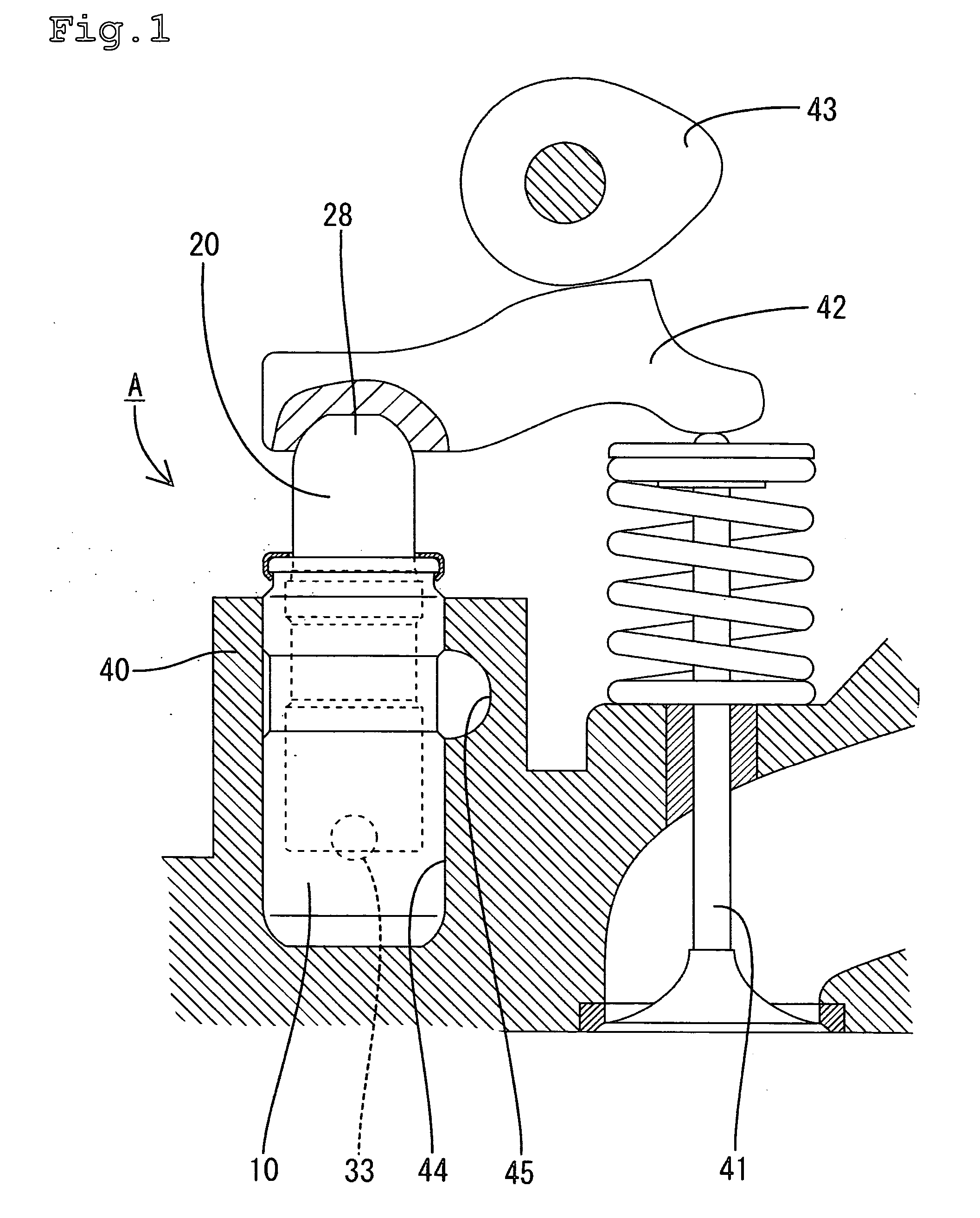
[0016] One embodiment of the present invention will be described with reference to the accompanying drawings. The hydraulic lash adjuster A, in accordance with the embodiment, is applied to a valve gear for an internal combustion engine. The valve gear will firstly be described. The valve gear comprises a valve 41, the lash adjuster A, a rocker arm 42 and a cam 43. With the rotation of the cam 43, the rocker arm 42 vertically oscillates with an upper end of the lash adjuster A serving as a fulcrum, thereby vertically moving the valve 41, as is well known in the art.

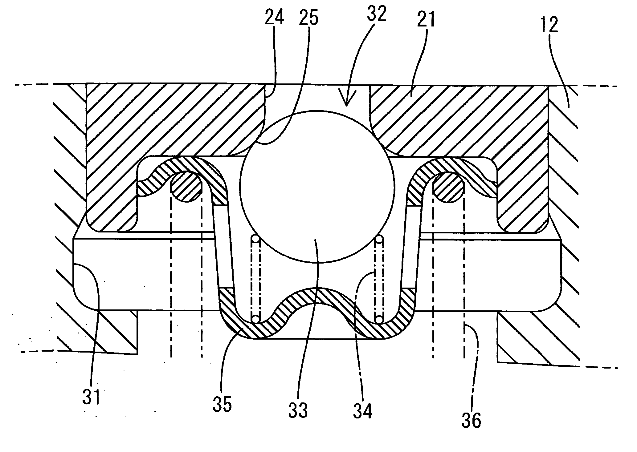
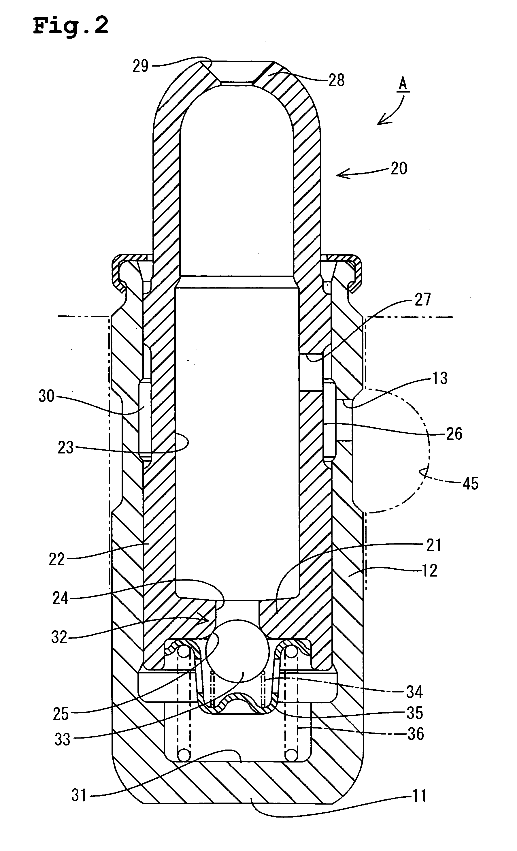
[0017] The lash adjuster will now be described. The lash adjuster A comprises a cylinder 10 and a plunger 20. The cylinder 10 is formed into the shape of a bottomed cylinder and includes a generally circular bottom wall 11 and a generally cylindrical circumferential wall 12 extending from a circumferential edge of the bottom wall 11. The cylinder 10 is fixed in a mounting hole 44, opening in an upper face of a cylinder h...


PUM


Abstract

A hydraulic lash adjuster for an internal combustion engine is disclosed. The hydraulic lash adjuster includes a low-pressure chamber defined in the plunger and filled with a hydraulic fluid and a high-pressure chamber filled with hydraulic fluid defined in a lower interior of the cylinder and partitioned by the bottom wall of the plunger from the low-pressure chamber. A valve port is formed through the bottom wall of the plunger so as to communicate with both the low-pressure and high-pressure chambers. The valve port has at the high-pressure chamber side an opening edge formed with a valve seat face. A valve element is provided in the high-pressure chamber so as to abut and depart from the valve seat face, thereby closing and opening the valve port. The valve element is made of a material having a specific gravity smaller than steel.

Description

BACKGROUND OF THE INVENTION [0001] 1. Field of the Invention [0002] This invention relates to a hydraulic lash adjuster used in valve gears or valve mechanisms for internal combustion engines. [0003] 2. Description of the Related Art [0004] A conventional hydraulic lash adjuster comprises a bottomed cylinder fixed to a cylinder head and a plunger accommodated in the cylinder so as to be vertically moved. The plunger has an upper end protruding from the cylinder. A rocker arm is supported on the upper end of the plunger. The interior of the plunger serves as a low-pressure chamber. A lower interior of the cylinder is divided by a bottom wall of the plunger, thereby serving as a high-pressure chamber. The bottom wall of the plunger is formed with a valve port of a check valve. The low-pressure chamber is filled with a hydraulic fluid supplied from a fluid supply passage via communication holes formed in the circumferential walls of the respective cylinder and plunger. Further, the hig...

Claims


Application Information

Patent Timeline
Patent Type & Authority Applications(United States)
IPC IPC(8): F01L1/14F01L1/18F01L1/24H01L27/15H01L29/26
CPCF01L1/185F01L2101/02F01L2101/00F01L1/2405F01L2301/02F01L2301/00
Inventor FUJII, HIROKIISHIKAWA, SHIZUOTERAMURA, MITSUYOSHI
Owner OTICS CORP
Why Eureka
Try Eureka