Eureka AIR delivers breakthrough ideas for toughest innovation challenges, trusted by R&D personnel around the world.

Timing gear flexible coupling

a flexible coupling and timing shaft technology, applied in oscillatory slide valves, machines/engines, hoisting equipment, etc., can solve the problems of lower galling potential, reduce the sliding friction, reduce the compressive bearing load, and increase the torque on the timing shaft.

Inactive Publication Date: 2005-08-25
AGAPIADES THOMAS
View PDF5 Cites 2 Cited by
  • Summary
  • Abstract
  • Description
  • Claims
  • Application Information

AI Technical Summary

Benefits of technology

[0006] It is the primary objective of the invention to lower the compressive bearing load between the interfacing surfaces of the disc valve and stator during the combustion ignition pressure spike event and thereby reduce the shearing impact on the lubricating film within the said interface reducing the sliding friction at this point in the engine cycle.
[0007] It is yet another objective of the invention to lower the disc rotational friction load to quicken engine acceleration response.

Problems solved by technology

Absorption of peak torque loads on the timing shaft by the resilient member during the peak combustion pressures when the sliding contact friction between the disc valve and stator are highest will lessen wear between the two surfaces and lower the potential for galling.

Method used


Image

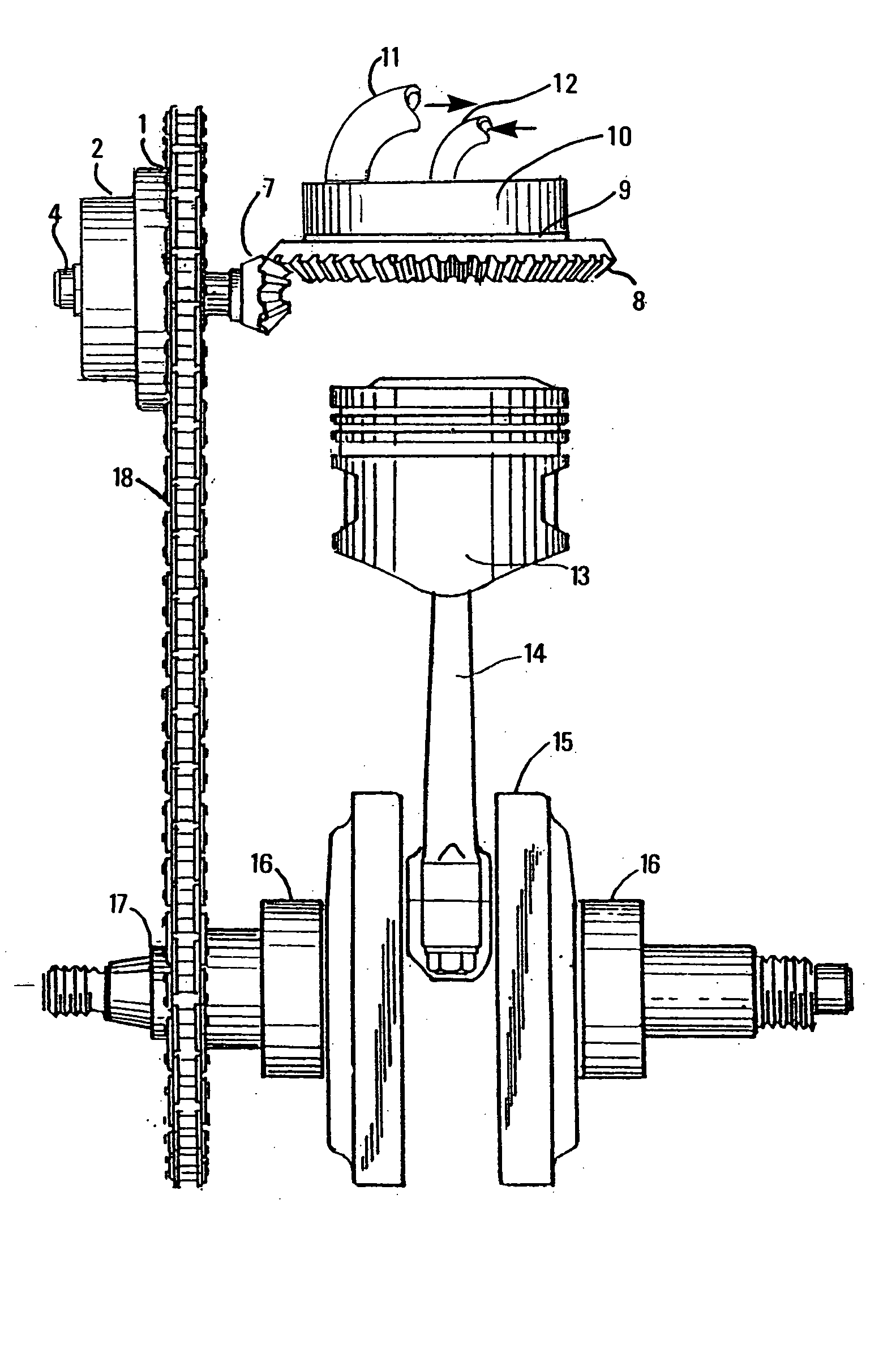
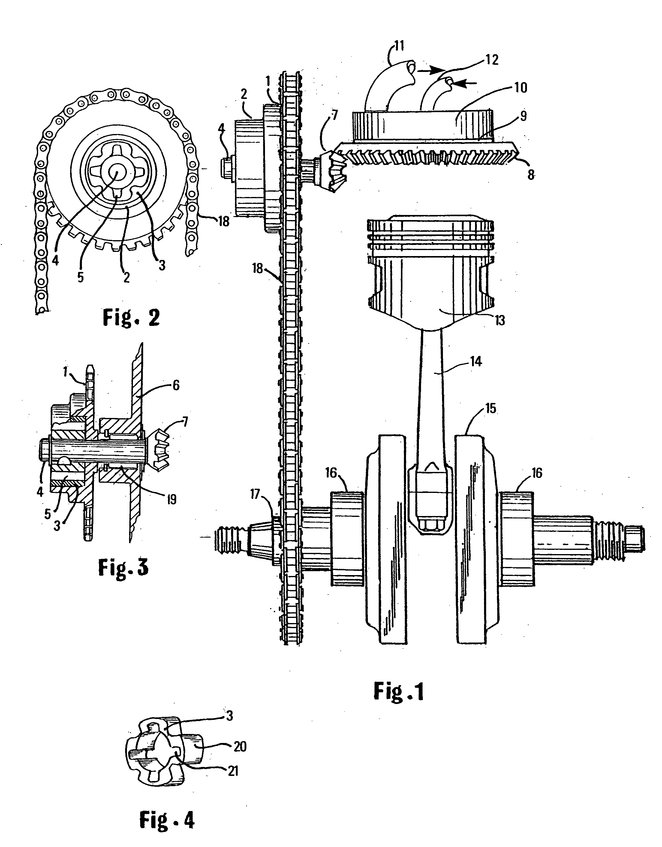
  • Timing gear flexible coupling
  • Timing gear flexible coupling

Examples


Embodiment Construction

[0013] The invention is a flexible coupling to be used in the opening and closing mechanism of a disc valve controlling the intake and exhaust flow circuits of an internal combustion engine.

[0014] Referring to FIG. 1 of the drawing sheet. FIG. 1 shows the moving components of the engine power train and shows the timing gear 1 and the timing gear hub 2 that holds a resilient member 3 (not shown) that is the flexural element of the timing gear 1 coupling. Timing gear 1 is rotatively mounted on timing shaft 4 which in turn is rotatively mounted in the supporting frame of an engine crankcase. Pinion bevel gear 7 is fixedly mounted at one end of timing shaft 4. Pinion bevel gear 7 engages bevel gear 8 which rotates disc valve 9 in circular sliding contact with stator 10 having a plurality of exhaust ports 11 and intake ports 12. Rotation of disc valve 9 opens and closes the said plurality of exhaust ports 11 and intake ports 12 synergistically in a manner corresponding to the reciprocati...


PUM


Abstract

The invention is a timing gear flexible coupling for operation of a disc valve rotatively mounted in an internal combustion engine cylinder head. Rotation of the disc valve periodically opens and closes a plurality of exhaust and intake ports in the stationary stator of the cylinder head in a sequential manner corresponding to the alternating order of the engine of the engine thermodynamic pressure cycle. The purpose of the flexible coupling is to momentarily slow the rotational velocity of the disc valve during the highest peak pressure of the engine combustion stroke during the ignition spike which exponentially reduces the rubbing contact frictional energy between the disc and stator. The primary purpose of the timing gear flexible coupling is to reduce the shearing impact across the lubricating film at the sliding interface between the disc valve and stationary stator comprising the engine intake and exhaust ports thereby decreasing frictional surface wear and permitting faster engine acceleration.

Description

BACKGROUND OF THE INVENTION [0001] The invention comprises an intervening resilient member that is mounted between the hub of an engine timing gear and timing shaft rotatively mounted in the cylinder head of a disc valve engine. The resilient member serves as a flexible coupling between the timing gear and the timing shaft. Flexible couplings are most generally used to provide shaft torque flexibility under heavy starting loads or to offset shaft misalignment. The resilient member in the present invention, while providing flexibility under torque loads is used in a unique manner that constitutes the novelty of this invention. The resilient member provides a means of lowering peak friction loads at the sliding interface between a stationary stator surface and the surface of a rotating disc valve operating within the fluctuating pressure field of an engine combustion chamber. [0002] Rotation of the said disc valve mounted within the engine combustion chamber periodically opens and clo...

Claims


Application Information

Patent Timeline
Patent Type & Authority Applications(United States)
IPC IPC(8): F01L1/344F01L7/00F01L7/06F16H55/14F16H57/00
CPCF01L1/022F01L1/026Y10T74/19633F01L7/06F16H55/14F01L1/3442
Inventor AGAPIADES, THOMAS
Owner AGAPIADES THOMAS
Why Eureka
Eureka Blog
Learn More