Thermal treatment equipment

a technology of thermal treatment equipment and equipment, which is applied in the direction of lighting and heating equipment, muffle furnaces, furnaces, etc., can solve the problems of inability to use equipment for mass production or industrialization of sic elements, inability to prevent undesirable surface irregularities, and inability to ionize the sic substrate with impurities. , to achieve the effect of high quality of sic elements, resistance value of sic substrate, and preventing undesirable surface irregularities

Inactive Publication Date: 2005-08-25
NAT INST OF ADVANCED IND SCI & TECH +2
View PDF6 Cites 11 Cited by
  • Summary
  • Abstract
  • Description
  • Claims
  • Application Information

AI Technical Summary

Benefits of technology

[0030] The thermal treatment equipment defined in claim 11 corresponds to the equipment according to any one of claims 1 through 10, wherein said equipment is programmed so that the SiC substrate is heated from a room temperature to about 1200° C. or higher in about 10 seconds to about 5 minutes, then maintained at such temperature for about 10 second to about 10 minutes and thereafter the SiC substrate is cooled to a temperature lower than about 1200° C. in about 10 seconds to about 30 minutes. With such an arrangement, a resistance value of the SiC substrate ion-implanted with impurities such as phosphor, nitrogen, aluminum or boron can be adequately lowered and, at the same time, evaporation of Si from the SiC substrate leading to the undesirable surface irregularities can be prevented. In this way, a high quality SiC element can be manufactured.
[0031] The thermal treatment equipment defined in claim 12 corresponds to the equipment according to claim 11, wherein said equipment is programmed so that the SiC substrate is previously heated to a temperature lower than about 1200° C., then heated from a room temperature to about 1200° C. or higher in about 10 seconds to about 5 minutes and thereafter cooled to a temperature lower than about 1200° C. in about 10 seconds to about 30 minutes. With such an arrangement also, a resistance value of the SiC substrate ion-implanted with impurities such as phosphor, nitrogen, aluminum and boron can be adequately lowered and, at the same time, evaporation of Si from the SiC substrate leading to the undesirable surface irregularities can be prevented. In this way, high quality SiC element can be manufactured.

Problems solved by technology

As has been described above, the thermal treatment equipment relying on the infrared lamp of prior art cannot be used for mass production of the SiC element from the SiC substrate having a diameter of several centimeters or larger.
While the thermal treatment method using the high frequency oven has already been proposed, this method results in that the temperature in the peripheral zone is relatively high while the temperature in the central zone is relatively low.
Eventually, the in-plane unevenness of the electric properties of the SiC element becomes so serious that such equipment cannot be used for mass production of or for industrialization of SiC elements.
In the case of heating the substrate at a high temperature by infrared lamps used with a quartz column, the conventional equipment has been accompanied also with another problem such that various impurities generated from the substrate stage may cling to the quartz column and obstruct transmission of the infrared rays.

Method used


Image

  • Thermal treatment equipment
  • Thermal treatment equipment
  • Thermal treatment equipment

Examples


Embodiment Construction

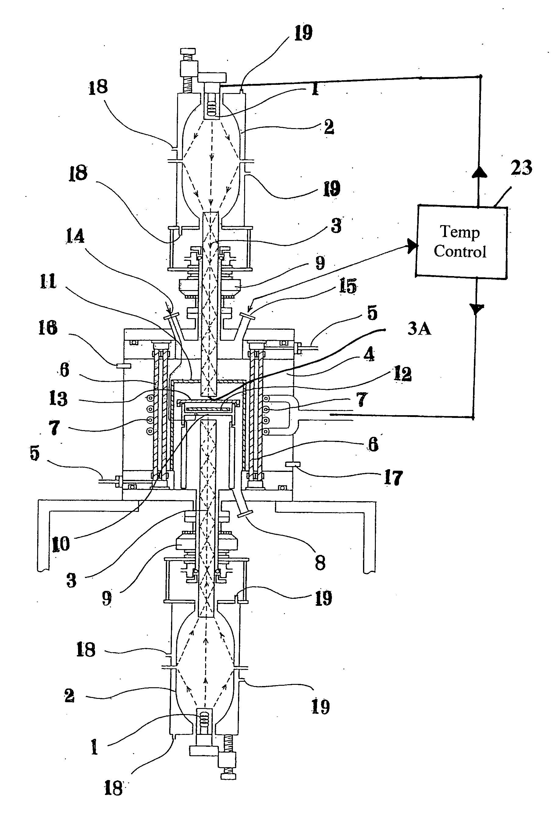
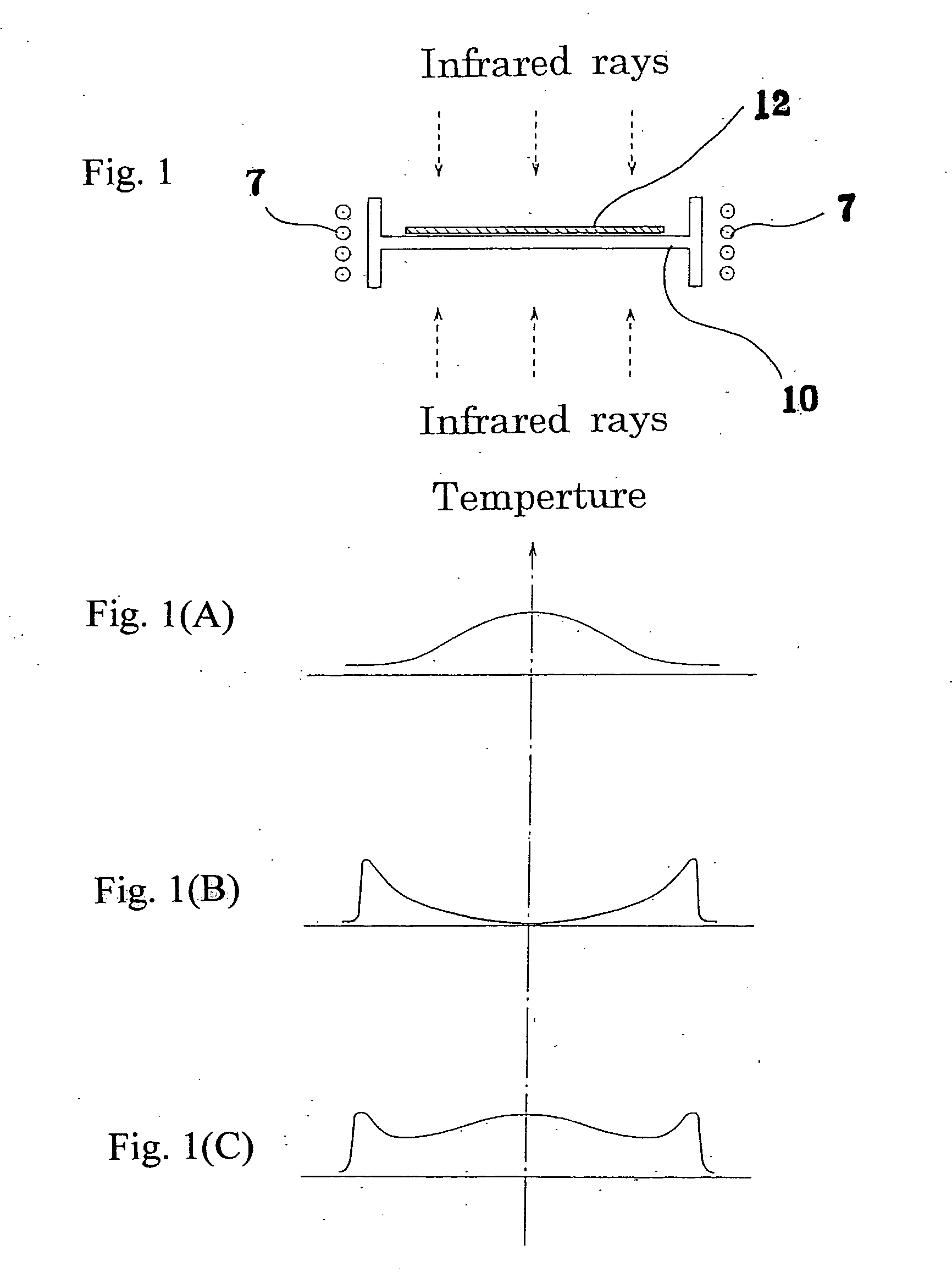
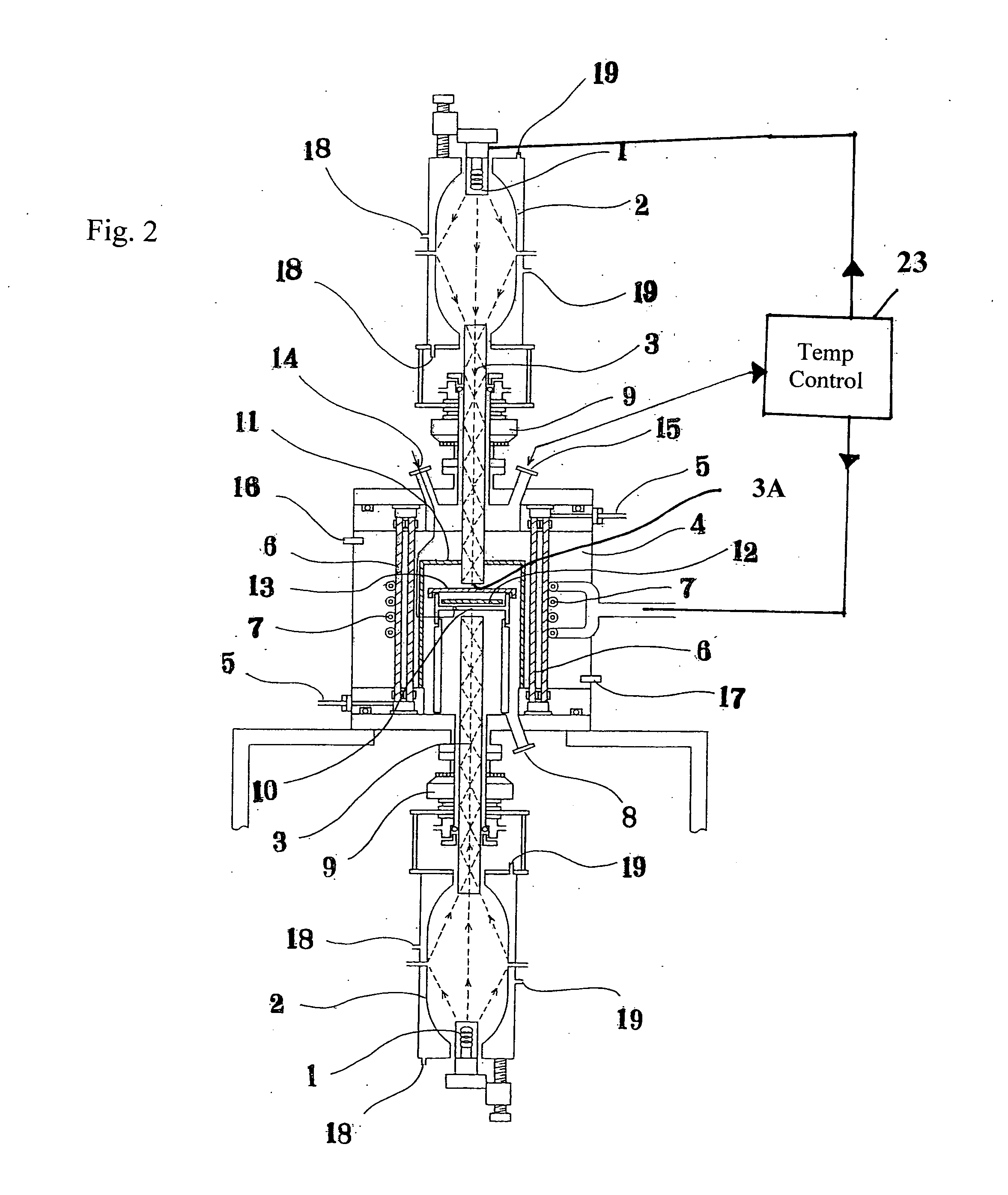
[0040]FIGS. 1 and 1(A)-1(C) illustrate the temperature distribution appearing as a result of heating by the infrared heating and / or the high frequency heating. FIG. 1(A) illustrates the temperature distribution appearing as a result of the infrared heating alone. FIG. 1(B) illustrates the temperature distribution appearing as a result of the high frequency heating alone, and FIG. 1(C) illustrates the temperature distribution as a result of both the infrared heating and the high frequency heating. FIG. 2 is a sectional view of a thermal treatment equipment according to the invention. FIG. 3 illustrates an example of a shielding structure. While the illustrated shielding structure is made of tantalum, this shielding structure may be made also of tungsten, molybdenum, carbon or SiC coated carbon. FIG. 4 illustrates placement of the infrared lamps. As illustrated, a plurality of infrared lamps are placed above and / or below a sample stage. FIG. 5 is a graph plotting a measured progressio...


PUM

PropertyMeasurementUnit
frequencyaaaaaaaaaa
distanceaaaaaaaaaa
temperatureaaaaaaaaaa

Abstract

Thermal treatment equipment for rapidly heating a SiC substrate having a diameter of several inches or larger to a temperature as high as 1200° C. or higher with a high in-plane evenness by heating a peripheral zone of a substrate using high frequency induction and by heating a central zone of the substrate using infrared lamps while the substrate and a stage thereof are covered with a shield plate.

Description

BACKGROUND OF THE INVENTION [0001] The present invention relates to thermal treatment equipment used in a manufacturing process in which a thermal treatment must be achieved in as short a time as possible, for example, by the process for activating thermal treatment after ion implantation of impurities into SiC. [0002] After impurities such as phosphor or nitrogen have been ion implanted into SiC substrate, a thermal treatment at a temperature as high as 1500° C. or higher is necessary in order to generate an impurities activating carrier. For such thermal treatment, it has already been reported to use a resistive heating oven, however, such resistive heating ovens inconveniently take an unacceptably long time until a temperature rises to about 1500° C. or higher. Furthermore, a duration of approximately 30 minutes is required for an effective thermal treatment and inevitably Si evaporates from the SiC substrate surface, resulting in irregularities on the substrate surface. In addit...

Claims


Application Information

Patent Timeline
Patent Type & Authority Applications(United States)
IPC IPC(8): H01L21/31C04B35/565C04B35/64F27B5/04F27B17/00H01L21/00H01L21/26
CPCC04B35/565C04B35/64H01L21/67115F27B17/0025F27B5/04
Inventor FUKUDA, KENJISENZAKI, JUNJINISHIZAWA, SHINICHIENDO, TOMOYOSHIYASHIMA, TERUYUKI
Owner NAT INST OF ADVANCED IND SCI & TECH
Why Eureka
Try Eureka