
Method of supplying electric power from shore to ship and system thereof

a technology of electric power supply and shore power, applied in the direction of emergency power supply arrangement, electric generator control, vessel auxiliary drives, etc., can solve the problems of short-time interruption of power supply, large amount of exhaust gas generated, air pollution and marine pollution, etc., and achieve the effect of low cost and easy introduction

Active Publication Date: 2005-08-25
JRCS
View PDF11 Cites 38 Cited by
  • Summary
  • Abstract
  • Description
  • Claims
  • Application Information

AI Technical Summary

Benefits of technology

[0009] The present invention has been made to overcome the above drawbacks of the prior arts, and accordingly the first object of the invention is to provide a method of supplying electric power from shore to a ship and a system thereof which are capable of preventing occurrence of power supply interruption when an onboard power source is changed over to a power source from shore, and further capable of securing a smooth operation of onboard control devices even on the way of changing over the power sources.
[0010] Further, the second object of the present invention is to provide a more economical method of supplying electric power from shore to a ship and a system thereof which do not require unnecessary wiring or modifications for changing over a power source supplied to the ship from onboard generators to the power source from shore.
[0011] The first aspect of the present invention according to the objects discloses a method of supplying electric power from shore to a ship with at least one generator, the ship being berthed in port, comprising: a first step of synchronizing the electric power from shore with electric power from the generator, a second step of carrying out temporary parallel operation of the electric power from shore and the electric power from the generator after the synchronizing of the first step, and a third step of shutting off the electric power from the generator to supply the electric power from shore to the ship after the temporary parallel operation of the second step. According to the first aspect of the invention, the power sources supplied to the ship can be changed over without occurrence of instantaneous interruption of power supply etc. Consequently, the changeover of the power sources has no adverse effect on onboard control devices, and thereby operations in the ship using electrical equipment can be performed continuously.

Problems solved by technology

However, in a case that the ship is berthed in port for a long period of time or a short period of time, when the ship has equipment consuming a large amount of electric power such as a freezing container, an engine (generator) of the ship must be kept in operation while the ship is berthed.
Consequently, a large amount of exhaust gas is generated, and it causes air pollution and marine pollution.
Thus, a short-time interruption of power supply is inevitable.
However, in the above method of changing over power sources, the electric power supply to the ship is interrupted temporarily, and consequently there have been problems such that onboard control devices including computers are reset.
In case of a large ship, the electric power necessary for the ship is supplied by driving several generators in parallel, and complicated computer control has been taken in order to allocate load to the generators while keeping frequencies of the plural generators constant.
In such case, adjusting the frequencies of the plural generators in operation to the frequency of the power source from shore has not been carried out generally, since such adjustment is very difficult.
Furthermore, when a large capacity of electric power is supplied from shore, a power line for receiving the electric power from shore must be connected to a main switchboard, which not only requires large-scale modifications inside the ship but also imposes burdens on an entire system of the ship.
In some cases, since the electric power from shore is too large, there is little space in the main switchboard to install necessary equipment.

Method used


Image

  • Method of supplying electric power from shore to ship and system thereof
  • Method of supplying electric power from shore to ship and system thereof
  • Method of supplying electric power from shore to ship and system thereof

Examples


Embodiment Construction

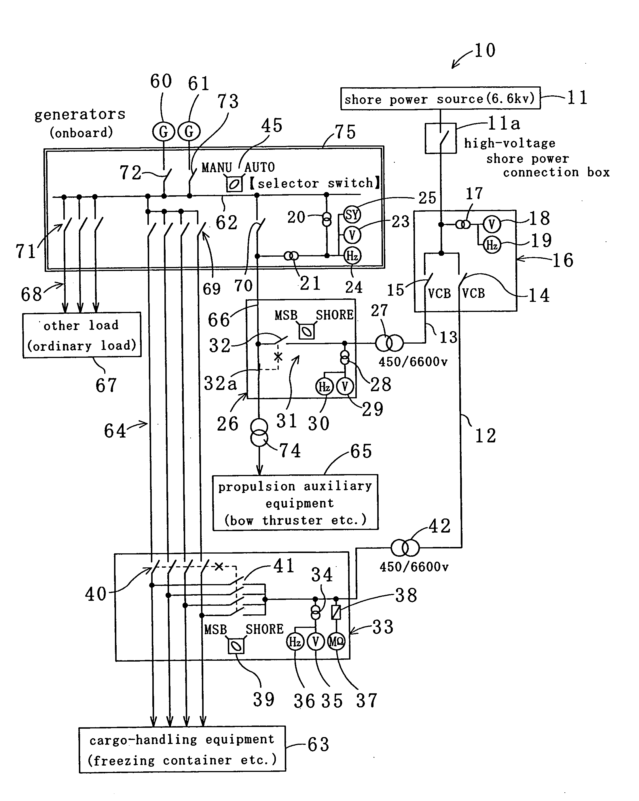
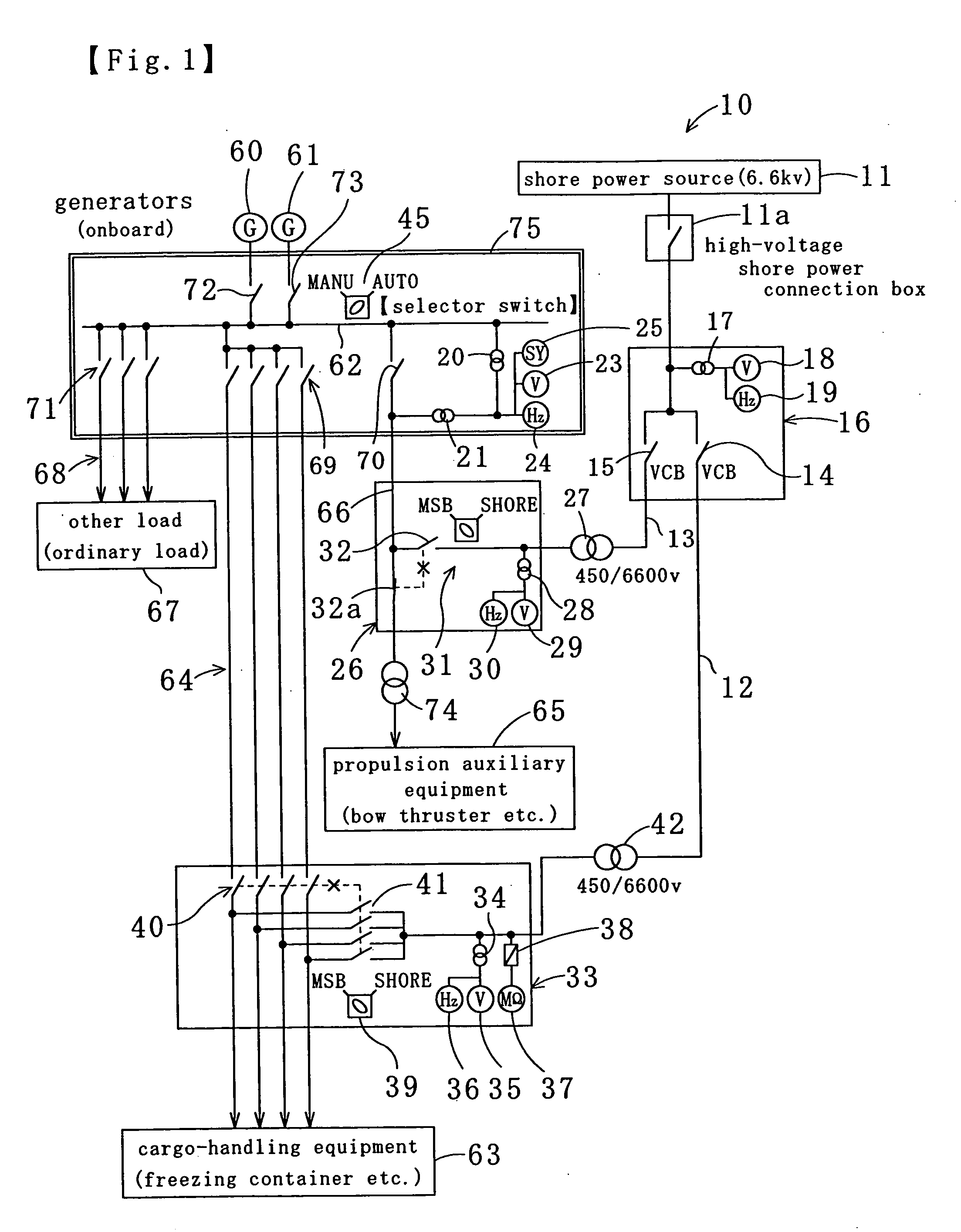
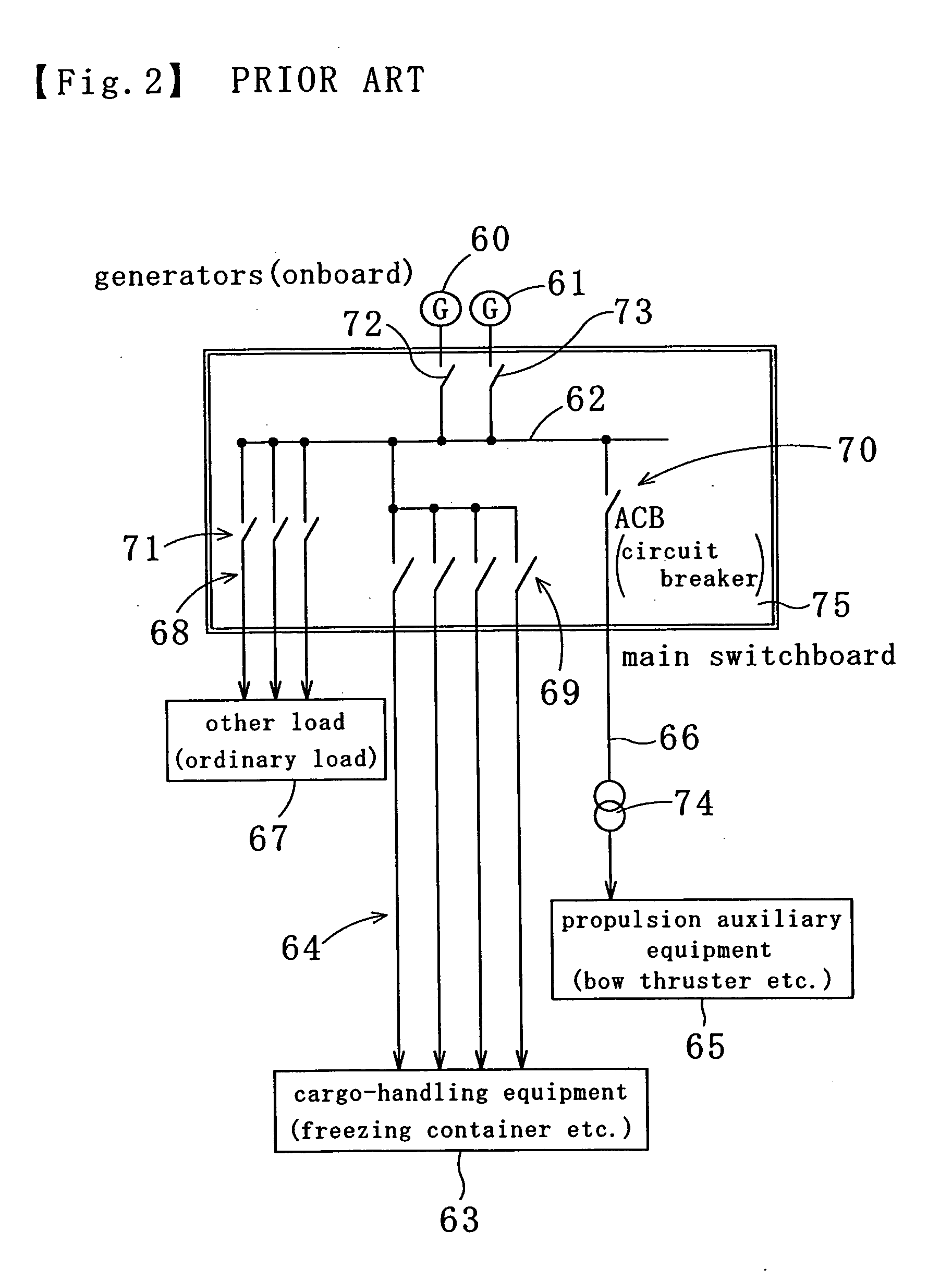
[0020] Referring to FIG. 1, the embodiment of the present invention will be explained hereinafter for the purpose of good understanding of the invention. In FIG. 1, each line is shown in a single line, but is normally composed of two power lines (in a case of single phase) or three power lines (in a case of three phases). In FIG. 1, the same constituent elements (parts and lines, for example) as those of the prior art illustrated in FIG. 2 are provided with the same numbers.

[0021] As illustrated in FIG. 1, an electric power supply system 10 for supplying electric power from shore to a ship according to one embodiment of the present invention has an electric power-receiving switchboard 16 which receives electric power 11 from shore (i.e., shore power 11) via a high-voltage shore power connection box (namely a connection terminal box) 11a. In the electric power-receiving switchboard 16, the electric power 11 from shore is divided into a first line 13 and a second line 12. Also, the e...


PUM


Abstract

A method and a system of supplying electric power from shore to a ship with generators 60, 61, the ship being berthed in port include: a first step of synchronizing the electric power 11 from shore with electric power from the generators 60, 61, a second step of carrying out temporary parallel operation of the electric power 11 from shore and the electric power from the generators 60, 61 after the synchronization, and a third step of shutting off the electric power from the generators 60, 61 to supply the electric power 11 from shore to the ship after the temporary parallel operation. According to the method and system, electric power supply interruption can be prevented when a shore power source is changed over to an onboard power source, and vice versa. Also, onboard control devices can be smoothly operated even on the way of changing over the power sources.

Description

BACKGROUND OF THE INVENTION [0001] 1. Technical Field [0002] The present invention relates to a method of supplying high-voltage and large-capacity electric power from shore to a ship berthed in port, and a system thereof. [0003] 2. Description of the Related Prior Art [0004] Generally, entire electric power for a ship is supplied by driving a generator with a turbine or engine as is known in e.g., Japanese Laid-Open Patent Publication 2000-217275. However, in a case that the ship is berthed in port for a long period of time or a short period of time, when the ship has equipment consuming a large amount of electric power such as a freezing container, an engine (generator) of the ship must be kept in operation while the ship is berthed. Consequently, a large amount of exhaust gas is generated, and it causes air pollution and marine pollution. In order to avoid such problems, it is recommended in recent years to stop the engine (generator) of the ship and to supply electric power from...

Claims


Application Information

Patent Timeline
Patent Type & Authority Applications(United States)
IPC IPC(8): B63J3/04H02J3/38H02J1/10H02J9/06H02J9/08
CPCB63J3/04B63J2003/043H02J9/08H02J9/066H02J9/061H02J2310/42
Inventor FUJITA, MASUMI
Owner JRCS
Learn More