Linear vibration motor using resonance frequency

a technology of resonance frequency and linear vibration, which is applied in the direction of mechanical vibration separation, machine supports, shock absorbers, etc., can solve the problems of shortening the lifetime of the motor, obtaining mechanical vibration, and occupying the volume of the elastic member except, so as to improve space efficiency, improve the lifetime and reliability of placement, and maximize the amplitude of vibration

Active Publication Date: 2005-08-25
MPLUS
View PDF15 Cites 136 Cited by
  • Summary
  • Abstract
  • Description
  • Claims
  • Application Information

AI Technical Summary

Benefits of technology

[0027] The present invention has been made to solve the foregoing problems of the prior art and it is therefore an object of the present invention to provide a linear vibration motor designed to vibrate itself by using resonance frequency in order to improve lifetime and reliability in placement of a conventional brush type vibration motor which rotates a rotor unit having unbalanced mass via the commutation between brushes and a commutator to obtain mechanical vibration. Further, the linear vibration motor using resonance frequency of the invention can improve space efficiency over that of a conventional vertical vibrator structure in order to maximize the amplitude of vibration in a fixed volume.

Problems solved by technology

Regardless of their designs, the above vibration motors generate rotational force to turn a rotary unit having an unbalanced mass thereby obtaining mechanical vibration, in which the rotational force is generally produced by supplying voltage to a rotor coil through the commutation by contacts of the brushes and the commutator.
Unfortunately, a brush type vibration motor incorporating such a commutator has following problems: In the rotation of the motor, brushes passing through a gap between segments of a commutator creates mechanical friction and an electric spark so that the brushes and the commutator are abraded to shorten the lifetime of the motor.
However, the portable vibrator 400 as shown in FIG. 3 also has following problems: The coil 420 is placed on the inside wall of the housing occupying a large space, and the elastic member is of a coil elastic member (i.e., an elastic member in which its plates are accumulated in thickness to occupy a volume if extruded to the maximum extent) so that the volume occupied by the elastic member except for the track drawn by its movement does not provide a space for increasing the volume of the vibrator in a fixed volume.
That is, the mass of the vibrator cannot be maximized failing to maximize the amplitude of vibration in a fixed volume.

Method used


Image

  • Linear vibration motor using resonance frequency
  • Linear vibration motor using resonance frequency
  • Linear vibration motor using resonance frequency

Examples


Embodiment Construction

[0046] Preferred embodiments of the invention will now be described in detail with reference to the accompanying drawings.

[0047]FIGS. 4 and 5 illustrate a linear vibration motor using resonance frequency of the invention, which will be described as follows.

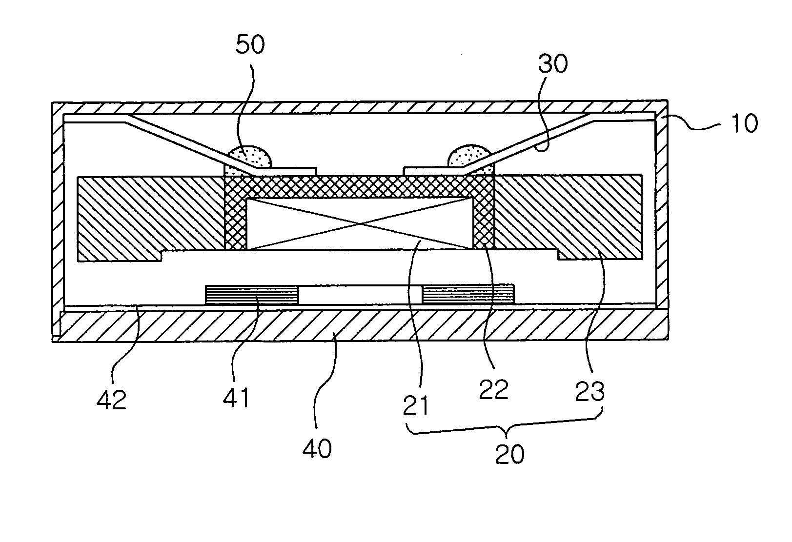
[0048] The present invention pertains to a linear vibration motor which obtains vibration by using the vertical resonance of a movable unit through the interaction of a magnetic force from a magnet with an electromagnetic force of a specific frequency from a coil assembly, and generally includes a movable unit 20, a base assembly 40 and a housing 10.

[0049] The movable unit 20 has a magnet 21, a yoke 22 for housing the magnet 21 and a weight 23 of a specific mass surrounding the flank of the yoke 22. The weight 23 preferably has a specific gravity larger than that of iron. This as a result increases the mass of the movable unit in a fixed volume to adjust resonance frequency associated with the mass of the weight thereby to maxi...


PUM


Abstract

A linear vibration motor comprising a movable unit, a base assembly having a coil assembly, a housing and an elastic member, in which the movable unit has the maximum mass from a fixed housing volume. The elastic member has the outer periphery fixed to the ceiling of the housing and the inner periphery fixed to the top of the movable unit opposed to the outer periphery. The elastic member is deformable to the extent that the outer and inner peripheries are shift to a coplanar position from a parallel position where they are spaced for a predetermined distance from each other. The core assembly is distanced downward from the movable unit or a predetermined gap.

Description

CLAIM OF PRIORITY [0001] This application claims the benefit of Korean Patent Application No. 2004-11907 filed on Feb. 23, 2004 and No. 2004-21673 filed on Mar. 30, 2004, in the Korean Intellectual Property Office, the disclosure of which is incorporated herein by reference. BACKGROUND OF THE INVENTION [0002] 1. Field of the Invention [0003] The present invention relates to a linear vibration motor using resonance frequency. More particularly, in a vertical vibrator which does not use a conventional vibration motor mechanism based upon brushes and a commutator, the linear vibration motor of the invention can minimize the volume of an elastic member except for the route of movement in order to maximize the amplitude of vibration in a fixed volume. [0004] 2. Description of the Related Art [0005] Communication instruments generally have a call receiving function as one of their essential functions. Typically, the call receiving function generates sound such as a melody and bell or vibr...

Claims


Application Information

Patent Timeline
Patent Type & Authority Applications(United States)
IPC IPC(8): B06B1/04F16F1/32F16F7/104F16M9/00H02K7/065H02K7/10H02K33/02H02K33/06H02K33/18H02K41/00
CPCB06B1/045F16F1/326H02K33/06H02K7/065F16F7/104
Inventor KWEON, SOON DOPARK, IL OUNGSON, YEON HOCHOI, JOONOH, HWA YOUNG
Owner MPLUS
Why Eureka
Try Eureka