Low leakage and data retention circuitry

a data retention circuit and low leakage technology, applied in logic circuits, power consumption reduction, logic circuits characterised by logic functions, etc., can solve the problems of three times reduction of leakage current, significant leakage power in the total power consumption of cmos circuits, dynamic power consumption and standby leakage current consumption, etc., to achieve low leakage and reduce power consumption

Active Publication Date: 2005-08-25
MOSAID TECH
View PDF20 Cites 24 Cited by
  • Summary
  • Abstract
  • Description
  • Claims
  • Application Information

AI Technical Summary

Benefits of technology

[0012] The invention addresses the above problems by providing systems and methods for low leakage, data retention circuitry. An integrated circuit includes first circuitry and sleep transistor circuitry. The first circuitry receives input signals and processes the input signals. The first circuitry also retains data in a sleep state that has low leakage. The sleep transistor circuitry is coupled to the first circuitry and receives a sleep signal that has a negative voltage. The sleep circuitry reduces power consumption of the first circuitry in the sleep state to have low leakage based on the sleep signal while retaining the data in the first circuitry.

Problems solved by technology

The total power consumed by an integrated circuit includes dynamic power consumption and standby leakage current consumption.
The challenge in designing an integrated circuit is to reduce the dynamic power and leakage power, while maintaining performance and cost goals for the integrated circuit.
When the threshold voltage for a CMOS transistor is reduced for higher performance, the leakage power is significant in the total power consumption of the CMOS circuit.
One problem with the transistor stack is that only a three times reduction in leakage current is achieved.
One problem with a multiple threshold design is that process complexity and costs are increased.
If separate body biases are applied to different NMOS transistors, the transistor cannot share the same well, which requires triple well technologies.
One problem is that well biasing consumes a lot of chip area and requires extra power supplies for each cell.
This technique also increases process complexity and the leakage reduction is not optimal.
One problem with sleep transistors is that if all logic has sleep transistors, the logic will lose their state information.

Method used


Image

  • Low leakage and data retention circuitry
  • Low leakage and data retention circuitry
  • Low leakage and data retention circuitry

Examples


Embodiment Construction

[0029] As shown in the exemplary drawings wherein like reference numerals indicate like or corresponding elements among the figures, exemplary embodiments of a system and method according to the present invention are described below in detail. It is to be understood, however, that the present invention may be embodied in various forms. Therefore, specific details disclosed herein are not to be interpreted as limiting, but rather as a basis for the claims and as a representative basis for teaching one skilled in the art to employ the present invention in virtually any appropriately detailed system, structure, method, process or manner.

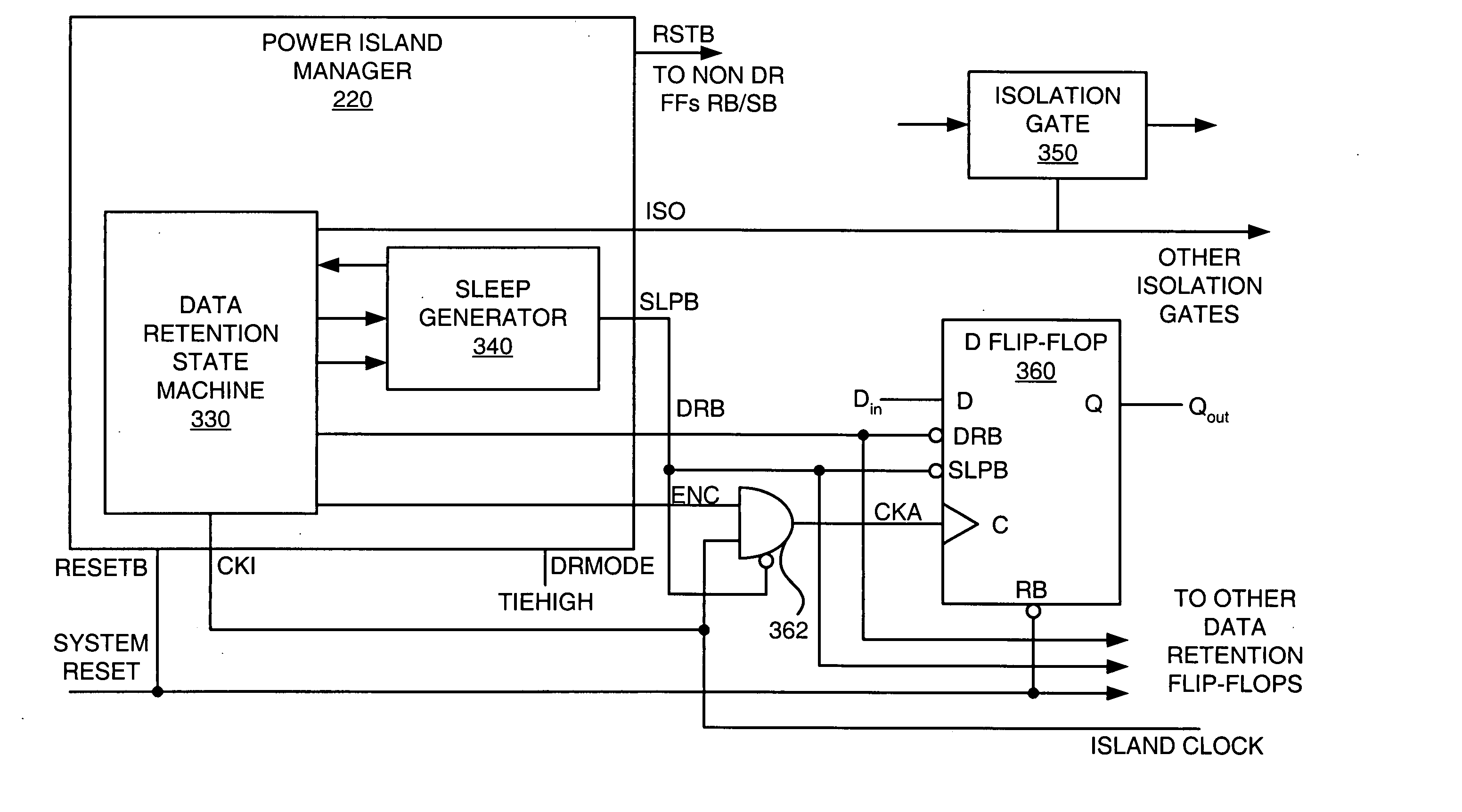
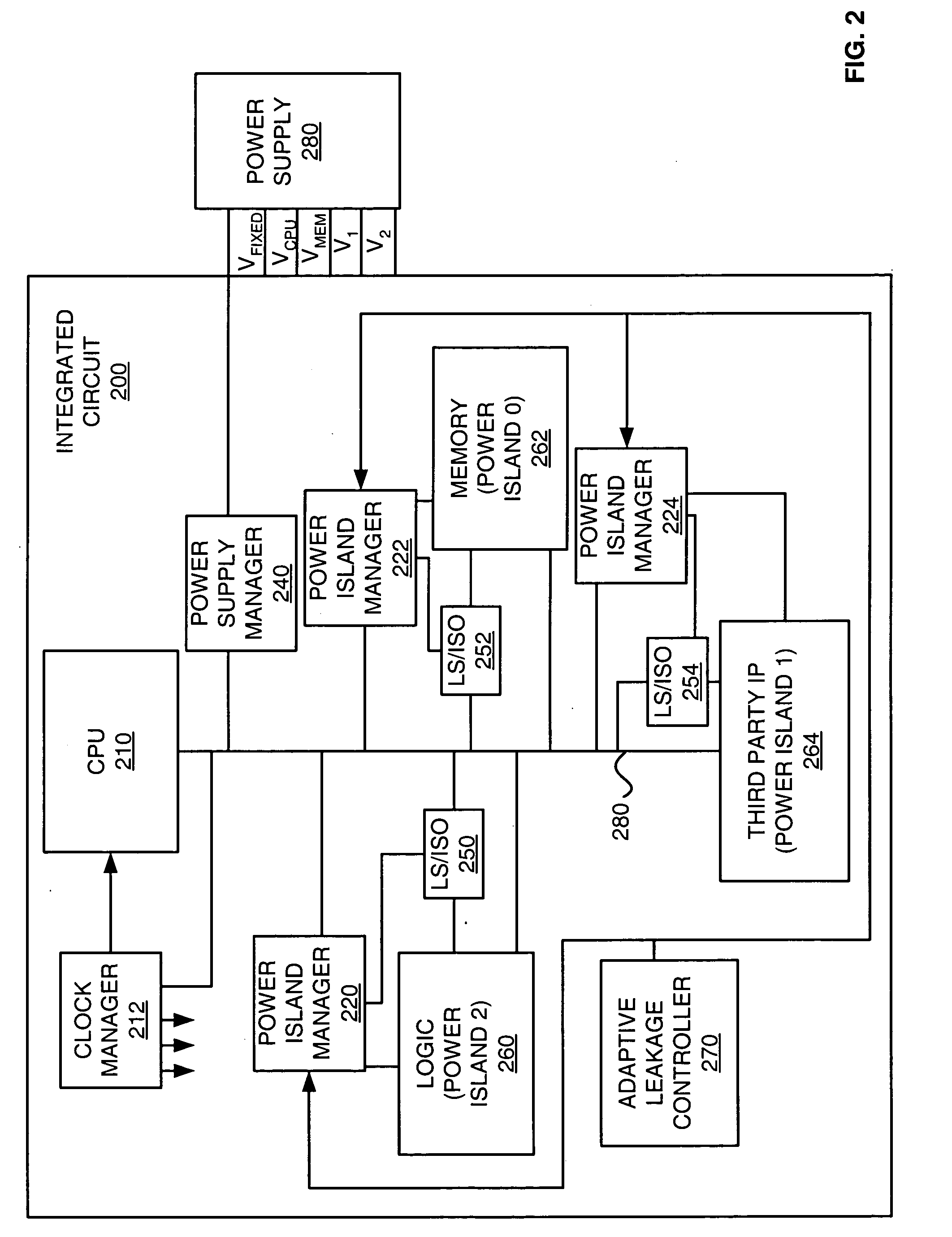
Power Island Manager—FIGS. 2-4

[0030] In some embodiments, an integrated circuit can be delineated into power islands. Power consumption can then be controlled within the power island. A power island manager provides control signals to the power island to control power consumption of the power island. In some embodiments, the low leakage, data retentio...


PUM


Abstract

An integrated circuit includes first circuitry and sleep transistor circuitry. The first circuitry receives input signals and processes the input signals. The first circuitry also retains data in a sleep state that has low leakage. The sleep transistor circuitry is coupled to the first circuitry and receives a sleep signal that has a negative voltage. The sleep circuitry reduces power consumption of the first circuitry in the sleep state to have low leakage based on the sleep signal while retaining the data in the first circuitry.

Description

CROSS-REFERENCE TO RELATED APPLICATIONS [0001] This application claims the benefit of U.S. Provisional Application Ser. No. 60 / 546,574 titled “Power Management and Power Savings in Integrated Circuits,” filed Feb. 19, 2004, which is hereby incorporated by reference. This application also claims the benefit of U.S. Provisional Application Ser. No. 60 / 586,565 titled “Systems and Methods for I / O Power Island Management and Leakage Control on Integrated Circuits,” filed Jul. 9, 2004, which is hereby incorporated by reference.BACKGROUND [0002] 1. Field of the Invention [0003] The present invention relates generally to integrated circuits, and more particularly to low leakage and data retention circuitry. [0004] 2. Description of the Prior Art [0005] Most integrated circuits have a design goal to reduce the overall power consumption. The total power consumed by an integrated circuit includes dynamic power consumption and standby leakage current consumption. The challenge in designing an i...

Claims


Application Information

Patent Timeline
Patent Type & Authority Applications(United States)
IPC IPC(8): H03K3/356H03K17/10H03K19/00
CPCG11C5/14H03K19/00315H03K17/102H03K3/356113H03K5/14G11C5/144H03K19/0016G11C5/148H02M3/07H03K3/0372H03K3/356086
Inventor HOBERMAN, BARRY A.HILLMAN, DANIEL L.WALKER, WILLIAM G.CALLAHAN, JOHN M.ZAMPAGLIONE, MICHAEL A.COLE, ANDREW
Owner MOSAID TECH
Why Eureka
Try Eureka