Method for characterizing mask defects using image reconstruction from X-ray diffraction patterns

Inactive Publication Date: 2005-08-25
RGT UNIV OF CALIFORNIA
View PDF12 Cites 29 Cited by
  • Summary
  • Abstract
  • Description
  • Claims
  • Application Information

AI Technical Summary

Benefits of technology

[0010] It is another object to provide a cost-efficient, non-de

Problems solved by technology

Localized defects in this thin film can significantly alter the reflected field and introduce errors in the printed image.
However, little work has been done to determine the out-of-plane defect position in a non-destructive way.
Other techniques, such as cross-sec

Method used


Image

  • Method for characterizing mask defects using image reconstruction from X-ray diffraction patterns
  • Method for characterizing mask defects using image reconstruction from X-ray diffraction patterns
  • Method for characterizing mask defects using image reconstruction from X-ray diffraction patterns

Examples


Embodiment Construction

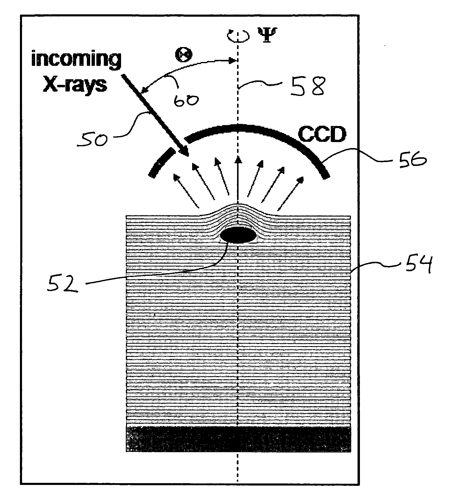
[0027] The present invention applies techniques for image reconstruction from X-ray diffraction patterns to produce three-dimensional images of defects in EUVL multilayer films. Techniques for image reconstruction from X-ray diffraction patterns are described in “Image reconstruction from electron and X-ray diffraction patterns using iterative algorithms: experiment and simulation,” Ultramicroscopy, Vol. 90, Issues 2-3, February 2002, Pages 171-195, incorporated herein by reference and in “Phase retrieval algorithms: a comparison,” Applied Optics, Vol. 21, No. 15, Aug. 1, 1982, Pages 2758-2769, incorporated herein by reference. The reconstructed image will give information about the defect position and the diffraction strength of the defect The positional information can be used to select the correct defect repair technique.

[0028] An experimental setup is shown in FIG. 4. An incoming X-ray beam 50 illuminates an area around a defect 52. It is preferable to use a focused beam. The b...


PUM


Abstract

The invention applies techniques for image reconstruction from X-ray diffraction patterns on the three-dimensional imaging of defects in EUVL multilayer films. The reconstructed image gives information about the out-of-plane position and the diffraction strength of the defect. The positional information can be used to select the correct defect repair technique. This invention enables the fabrication of defect-free (since repaired) X-ray Mo—Si multilayer mirrors. Repairing Mo—Si multilayer-film defects on mask blanks is a key for the commercial success of EUVL. It is known that particles are added to the Mo—Si multilayer film during the fabrication process. There is a large effort to reduce this contamination, but results are not sufficient, and defects continue to be a major mask yield limiter. All suggested repair strategies need to know the out-of-plane position of the defects in the multilayer.

Description

[0001] The United States Government has rights in this invention pursuant to Contract No. W-7405-ENG-48 between the United States Department of Energy and the University of California for the operation of Lawrence Livermore National Laboratory.BACKGROUND OF THE INVENTION [0002] 1. Field of the Invention [0003] The present invention relates to defect repair, particularly in EUVL multilayers, and more specifically, it relates to methods for determining the location of such defects. [0004] 2. Description of Related Art [0005] Extreme ultraviolet (EUV) lithography is the top contender for next generation lithography in high-volume semiconductor manufacturing for the 35 nm node and beyond. It utilizes 13.4 nm radiation as the exposure light source and employs Mo—Si multilayer stacks as the reflector for both optic mirrors and mask blanks. [0006] Referring to FIG. 1A, EUV mask blanks are fabricated by depositing a reflective Mo / Si multilayer film 10 onto a super-polished substrate 12. Loc...

Claims


Application Information

Patent Timeline
IPC IPC(8): G01N21/00G01N21/47G01N21/95G03F1/00
CPCB82Y10/00B82Y40/00G01N21/4788H01J2237/31744G03F1/24G03F1/74G01N21/9501G03F1/84
Inventor HAU-RIEGE, STEFAN PETER
Owner RGT UNIV OF CALIFORNIA
Why Eureka
Try Eureka