Data transfer method and system

Inactive Publication Date: 2005-08-25
SOCIONEXT INC
View PDF8 Cites 28 Cited by
  • Summary
  • Abstract
  • Description
  • Claims
  • Application Information

AI Technical Summary

Benefits of technology

[0024] In the data transfer method and system described above, when cache data of the controller is transferred to the nonvolatile memory such as a flash memory, the volatile memory such as a pseudo SRAM is used as a temporary buffer so as to avoid the situation in which the controller is bound for a long time period corresponding to

Problems solved by technology

An SRAM is comprised of 6 transistors per memory cell, and, thus, the number of devices for storing 1-bit data is relatively large compared to a DRAM (Dynamic Random Access Memory), for example, resulting in difficulties in achieving a large memory capacity.
Accordingly, it is extremely difficult to attain such highly sophisticated services as described above by use of a system employing only SRAMs.
Each of these memories is optimized according to its usage, and its replacement is regarded as a difficult challenge.
The SRAM is characterized by its low standby current consumption and high-speed read/write access, but is not suitable for achieving a large memory capacity.
Accordingly, the SRAM is suited to store cache data of small size, but is not suited to store programs and data, which ar

Method used


Image

  • Data transfer method and system
  • Data transfer method and system
  • Data transfer method and system

Examples


Embodiment Construction

[0037] In the following, embodiments of the present invention will be described with reference to the accompanying drawings.

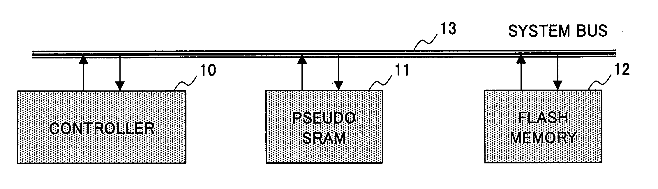
[0038]FIG. 1 is a block diagram showing the configuration of an information processing system according to the present invention.

[0039] The information processing system of FIG. 1 is a memory system used in a mobile phone, for example, and includes a controller 10, a pseudo SRAM 11, a flash memory 12, and a system bus 13. The flash memory 12 is used to store therein programs to be executed and data to be processed by the controller 10. The pseudo SRAM 11 is used as a work memory area that is used at the time of moving picture processing or the like by the controller 10. Here, a memory serving as the work memory area suffices if it is a large size RAM, and is not limited to the pseudo SRAM. For example, a DRAM (Dynamic Random Access Memory), SDRAM (Synchronous Dynamic Random Access Memory), FRAM (Ferroelectric Random Access Memory), or the like may accomplish ...


PUM


Abstract

A data transfer method and system are provided that prevent the length of a time required for writing to a flash memory from appearing on the surface as a system operation when the flash memory is used in place of an SRAM. The method of transferring data includes the steps of writing data from a controller to a volatile memory, placing the volatile memory in a transfer state, transferring the data from the volatile memory in the transfer state to a nonvolatile memory, and releasing the volatile memory from the transfer state in response to confirming completion of the transfer of the data.

Description

CROSS-REFERENCE TO RELATED APPLICATION [0001] This is a continuation of International Application No. PCT / JP03 / 08211, filed on Jun. 27, 2003, the entire contents of which are hereby incorporated by reference.BACKGROUND OF THE INVENTION [0002] 1. Field of the Invention [0003] The present invention generally relates to data transfer methods and systems for use in information processing systems, and particularly relates to a data transfer method and system for use in an information processing system which employs a plurality of different types of memory devices. [0004] 2. Description of the Related Art [0005] Together with a recent increase in the sophistication of service functions provided in the field of mobile communications such as cellular phones, the size of data being handled increases, resulting in a need for a larger memory volume. In mobile phones, for example, service functions are provided for moving picture data (movie functions), still images (camera functions), game fun...

Claims


Application Information

Patent Timeline
IPC IPC(8): G06F12/00G06F12/08G06F13/16G11C7/10G11C8/00G11C11/406G11C16/12G11C16/34
CPCG06F12/0804G06F2212/2022G11C7/1006G11C16/3454G11C11/40615G11C16/06G11C11/406G06F12/00G06F13/16
Inventor FUJIOKA, SHINYASATO, KOTOKUIKEDA, HITOSHIOKUYAMA, YOSHIAKIOHNO, JUN
Owner SOCIONEXT INC
Why Eureka
Try Eureka