Servo control system for movable body, and laser drilling machine

a technology of servo control system and laser drilling machine, which is applied in the direction of electric controllers, ignition automatic control, instruments, etc., can solve the problems of potential deterioration of positioning accuracy, production of residual vibrations, and deterioration of positional accuracy of drilling, so as to improve throughput and accuracy, high speed, and the effect of high accuracy

Active Publication Date: 2005-08-25
HITACHI SEIKO LTD
View PDF10 Cites 13 Cited by
  • Summary
  • Abstract
  • Description
  • Claims
  • Application Information

AI Technical Summary

Benefits of technology

[0023] According to the present invention, the movable member can be positioned at high speed with high accuracy. Therefore, the present invention can improve, for example, the throughput and accuracy of machining.

Problems solved by technology

If any certain spectrum component coincides with a resonance frequency of the above-mentioned torsional vibrations in this case, its vibration mode is considered to result in the production of residual vibrations so that the positional accuracy of drilling would be deteriorated.
A shorter command interval, however, leads to the inclusion of more high-frequency components in the frequency spectrum of an angle command pattern, so that due to high-order vibration modes of a drive shaft, residual vibrations tend to occur, resulting in a concern about potential deterioration in the positioning accuracy.
Nonetheless, the above-described conventional techniques indicate no means for the realization of high-speed and high-accuracy positioning without extending the positioning time for various angle command patterns.
The conventional techniques, however, shows no means for stably controlling small the settling responses for positioning, which begin from initial state values that can vary widely.

Method used


Image

  • Servo control system for movable body, and laser drilling machine
  • Servo control system for movable body, and laser drilling machine
  • Servo control system for movable body, and laser drilling machine

Examples


Embodiment Construction

[0034] The present inventors have found that a vibrational settling response, which takes place in conventional steerable mirror control systems, can be attributed to an influence from the initial state values in the first-order torsional vibration mode.

[0035] A description will hereinafter be made about an application of the present invention to a steerable mirror control system.

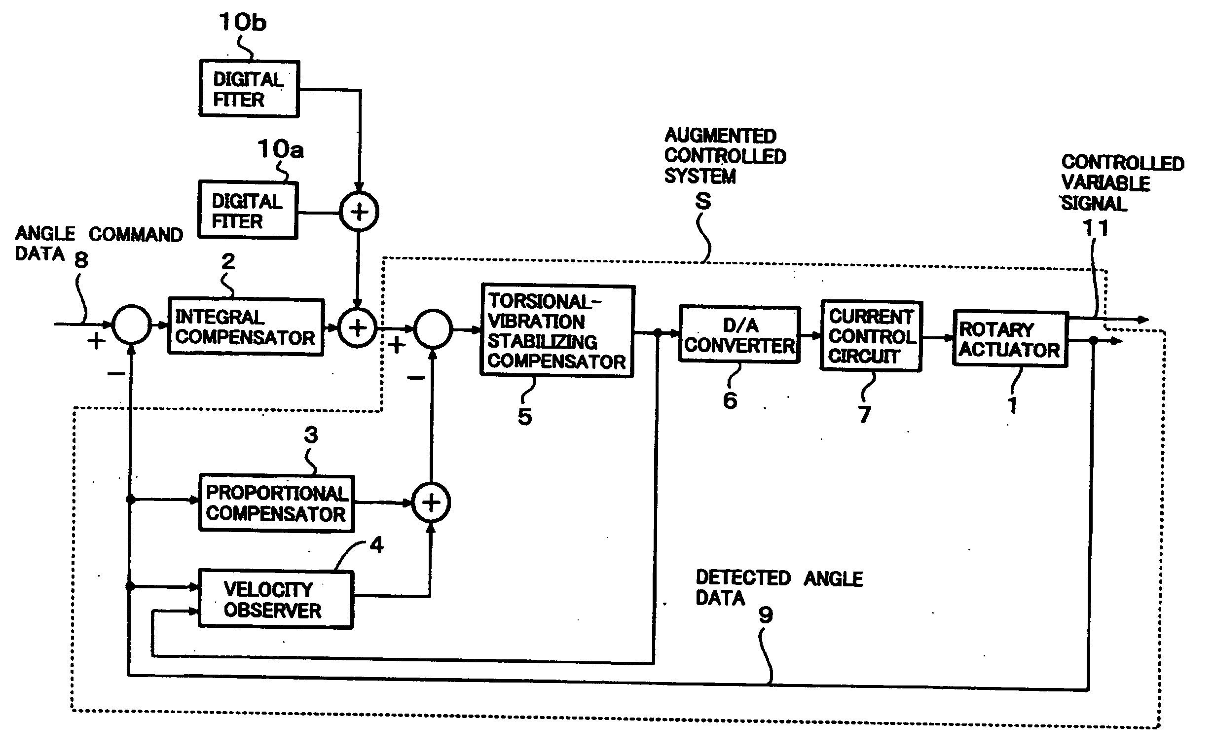
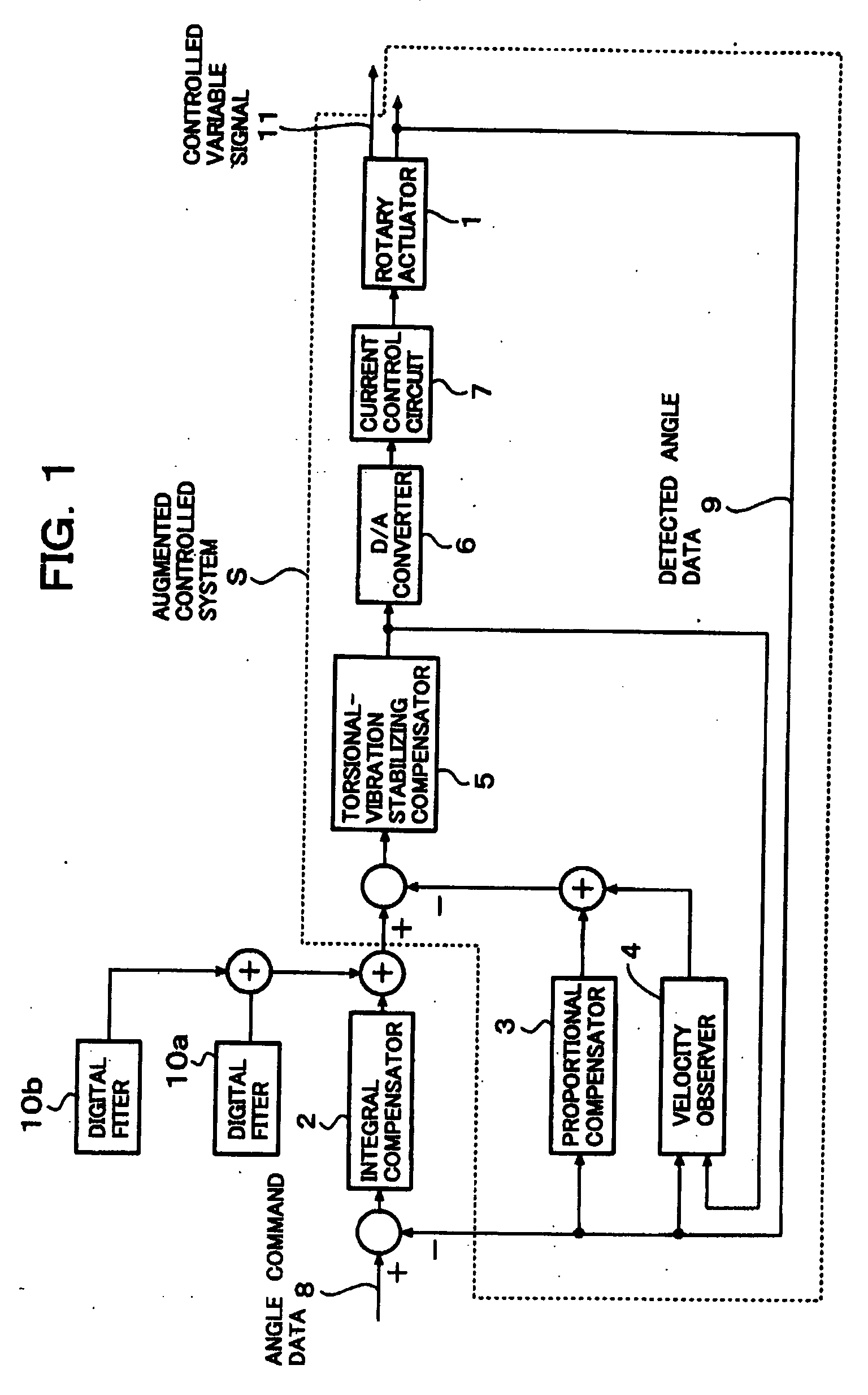
[0036] A steerable mirror control system according to an embodiment of the present invention as illustrated in FIG. 1 is realized by a digital control firmware making use of a microprocessor (not shown), and in respect to an integral compensator 2, a proportional compensator 3, a velocity observer 4, a torsional-vibration stabilizing compensator 5, a digital filter 10a and a digital filter 10b, processing operations are written in parts of a program which the microprocessor executes. These processing operations are performed at discrete times of a predetermined sampling period (hereinafter called “discret...


PUM

PropertyMeasurementUnit
angleaaaaaaaaaa
timeaaaaaaaaaa
angleaaaaaaaaaa

Abstract

A difference between each position command data outputted in a form of a step signal from a high-level controller and its corresponding detected position data of a movable body is integrated by an integral compensator to position the movable body. Assuming, for example, that the movable body is a steerable mirror, digital filters are arranged to compensate the value of an initial state of an angular displacement and the value of an initial state of an angular velocity, respectively, and respective impulse responses of the digital filters as additional input elements are added to an output terminal of the integral compensator. For higher effectiveness, internal state variables of the digital filters can desirably be cleared to zero whenever an angle (position) command data is received.

Description

FIELD OF THE INVENTION [0001] This invention relates to a servo control system for a movable body, which detects the position of the movable body and controls the movable body such that the movable body traces designated target values, and also to a laser drilling machine which controls a moving unit by such a servo control system for a movable body. DESCRIPTION OF THE BACKGROUND [0002] For a laser drilling machine which performs drilling, for example, in a fabrication process of a printed circuit board, a positioning control system is required to sequentially irradiate a laser beam to plural positions of a work under drilling. A steerable mirror control system is often used to materialize a high drilling throughput and high-accuracy drilling. [0003] In general, a laser drilling machine is a numerical control (NC) machine having a hierarchical control structure, and a steerable mirror control system is included in its lowest level hierarchy. In a control system of high level hierarc...

Claims


Application Information

Patent Timeline
Patent Type & Authority Applications(United States)
IPC IPC(8): G02B26/10B23K26/10G05B13/02G05D3/12
CPCB23K26/10B23K26/4025B23K26/381B23K26/382B23K2103/50
Inventor TOYAMA, SOUICHIOKUBO, YAICHIHIRAI, HIROMUIWASAKI, MAKOTOKAWAFUKU, MOTOHIROHIROSE, NORIAKI
Owner HITACHI SEIKO LTD
Why Eureka
Try Eureka