Micromechanical high-pressure sensor

a high-pressure sensor, micro-mechanical technology, applied in the direction of fluid pressure measurement, fluid pressure measurement by electric/magnetic elements, instruments, etc., can solve problems such as membrane deformation, and achieve the effects of increasing sensitivity, increasing sensitivity, and stabilizing the entire layer system

Inactive Publication Date: 2005-09-01
ROBERT BOSCH GMBH
View PDF4 Cites 58 Cited by
  • Summary
  • Abstract
  • Description
  • Claims
  • Application Information

AI Technical Summary

Benefits of technology

[0007] The at least partial crystallization causes the pressure sensor to become more stable with respect to environmental influences. For instance, the pressure sensor may be used in temperatures of up to 400° C.
[0010] In an embodiment of the present invention, an SiOx layer as insulating layer is deposited on the steel membrane. Furthermore, it may be provided that the NiCr(Si) layer be deposited in a sputtering process. In an advantageous manner, a photochemical method in which the NiCr(Si) layer is masked by a photo layer has proven useful as conventional method for the patterning. Ageing of the measuring element or the entire micromechanical pressure sensor has shown to be advantageous as well.
[0011] During at least one annealing step, the measuring element, for instance, undergoes a thermal treatment, which simulates artificial ageing. This ageing process stabilizes the measuring element or the pressure sensor with respect to environmental influences.
[0014] Due to the crystallization or the partial crystallization, which begins to any noticeable extent only at a temperature of >350° C., the specific resistance of the resistance layer that includes the NiCr(Si) layer is able to be reduced by approximately 10% according to the present invention. In addition, an increase in the sensitivity with respect to the k factor of approximately 35% can be observed. Because of the increased sensitivity, fewer demands are therefore placed on the evaluation electronics. Furthermore, lower mechanical loading of the deformation body, i.e., the membrane, will be required to generate a measured variable representing the applied pressure. This allows an optimization of the configuration with respect to linearity and hysteresis, among others. As a result of the higher k factor, an increase in the membrane thickness may be achieved while the output signal remains unchanged. In this case, constant manufacturing tolerances will result in less variance of the sensor sensitivity in the membrane production.
[0015] The thermal treatment of the sensor at a temperature of >350° C. considerably extends the possible operating temperature of the sensor. Stable behavior at temperatures of up to just below 400° C. is conceivable, for instance. At the same time, the production method of a micromechanical pressure sensor according to the present invention is able to be carried out in a cost-effective manner since the described high-temperature annealing step may be realized as extension of a temperature step that is already part of a thin-layer process. As a result, there is also no impediment to the use in a large-scale manufacturing process.

Problems solved by technology

A pressure applied at the membrane or a pressure differential applied at the different sides of the membrane results in deformation of the membrane.

Method used


Image

  • Micromechanical high-pressure sensor
  • Micromechanical high-pressure sensor

Examples


Embodiment Construction

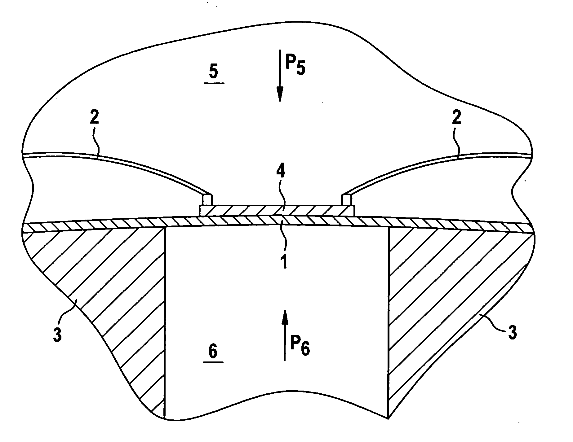
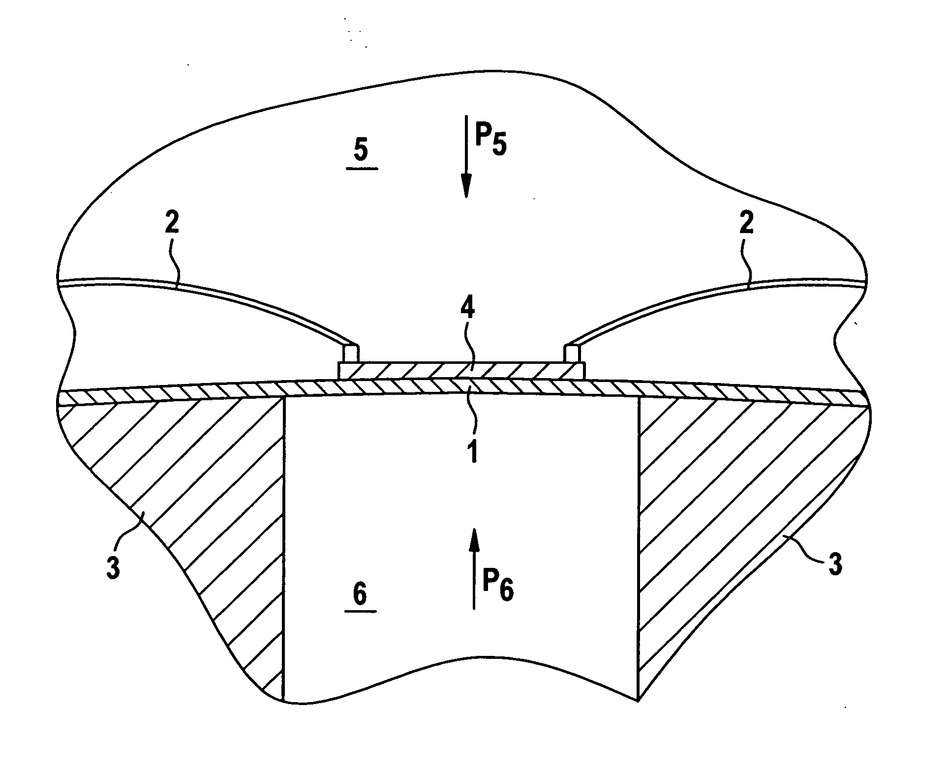
[0018] The FIGURE schematically illustrates the structure of a pressure sensor as it is produced in the present invention. A membrane 1 is mounted in a frame 3 in such a way that a gas volume 5 having pressure p5 is separated from a gas volume 6 having pressure p6. Membrane 1 may be made of the same material as the frame or it may be produced from a completely different material. No pressure equalization through membrane 1 is able to take place between gas volume 5 and gas volume 6. Located on membrane 1 is a resistance layer 4, which may be made of semiconducting or conducting materials. For evaluation of the measured variables that are detected by resistance layer 4, contactings 2 are affixed on the resistance layer, which allow the measured variables to be forwarded for analysis.

[0019] The method of functioning of the illustrated pressure sensor via resistance layer 4 will be explained briefly in the following.

[0020] In response to a pressure change on one side of membrane 1, f...


PUM

PropertyMeasurementUnit
temperatureaaaaaaaaaa
temperaturesaaaaaaaaaa

Abstract

A micromechanical pressure sensor and a method for producing a micromechanical pressure sensor. This pressure sensor has at least one membrane and a measuring element situated on the membrane. A pressure applied at the membrane or a pressure differential applied at the different sides of the membrane results in deformation of the membrane. Simultaneous with the deformation of the membrane, the measuring element is subjected to elastic elongation and / or compression. In a piezo-sensitive component, such elastic elongation and / or compression generates a measured variable in the measuring element, which represents the applied pressure or the applied pressure differential at the membrane. It is provided in this context that the measuring element have at least partially a NiCr(Si) layer. Due to an at least partial crystallization in the production of the micromechanical pressure sensor, this NiCr(Si) layer has more advantageous piezoelectrical characteristics than an amorphous NiCr(Si) layer.

Description

FIELD OF THE INVENTION [0001] The present invention is based on a method and a device for producing a micromechanical pressure sensor. BACKGROUND INFORMATION [0002] High-pressure sensors are utilized in many systems such as in automation technology and in the automotive field. In the automotive field, the high-pressure sensors are used in gasoline-direct injection, common rail diesel-direct injection, electronic stability programs and in electro-hydraulic brakes, among others. [0003] In addition to capacitive measuring methods for pressure sensors, piezoresistive methods are known where, for instance, metal resistors are interconnected in the form of a Wheatstone bridge on a suitably designed steel membrane. Elastic elongation or compression of the resistors produces detuning of the bridge, the detuning generating a measured variable which represents the applied pressure. In applications in the motor vehicle field, for instance, such high-pressure sensors are required to have high s...

Claims


Application Information

Patent Timeline
Patent Type & Authority Applications(United States)
IPC IPC(8): B32B17/06G01L9/00G01L1/22G01L9/08H01L29/84
CPCG01L9/08G01L9/0055
Inventor MOELKNER, THOMASHENN, RALFSTEINER, WERNERDIDRA, HANS-PETERCUTULI, PHILIPKLOPF, FRANK
Owner ROBERT BOSCH GMBH
Why Eureka
Try Eureka