Point diffraction interferometer and exposure apparatus and method using the same

a technology of interferometer and point diffraction, applied in the direction of photomechanical equipment, instruments, optics, etc., can solve the problems of insufficient precision of conventional surface precision measuring apparatus to measure such a highly precise surface shape, and the inability of other than pinholes to maintain a constant polarization state, so as to achieve the effect of precisely measuring the optical performance of a target optical system and reducing the offs

Inactive Publication Date: 2005-09-01
CANON KK
View PDF5 Cites 6 Cited by
  • Summary
  • Abstract
  • Description
  • Claims
  • Application Information

AI Technical Summary

Benefits of technology

[0007] The present invention is directed to a PDI, an exposure apparatus and method using the PDI, and a device manufacturing method, which can reduce an offset between an ideal spherical wave and an exited wave front from a pinhole, and precisely measure the optical performance of a target optical system.

Problems solved by technology

The conventional surface precision measuring apparatus is insufficient in precision to measure such a highly precise surface shape.
However, the optical element other than the pinhole cannot maintain a constant polarization state due to the polarization dependency, such as a reflection and refraction, or provide precise measurements.

Method used


Image

  • Point diffraction interferometer and exposure apparatus and method using the same
  • Point diffraction interferometer and exposure apparatus and method using the same
  • Point diffraction interferometer and exposure apparatus and method using the same

Examples


Embodiment Construction

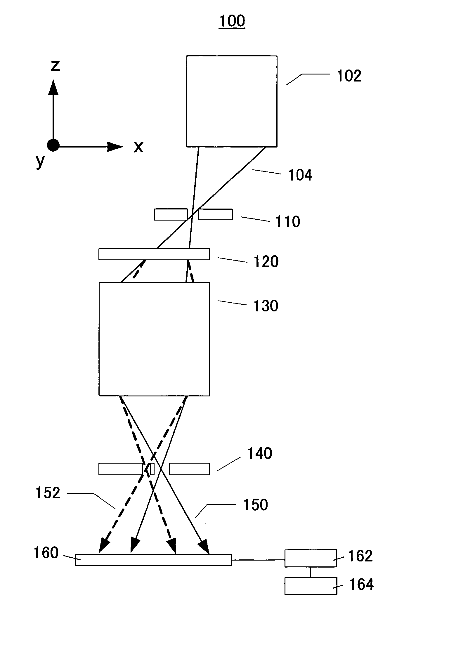
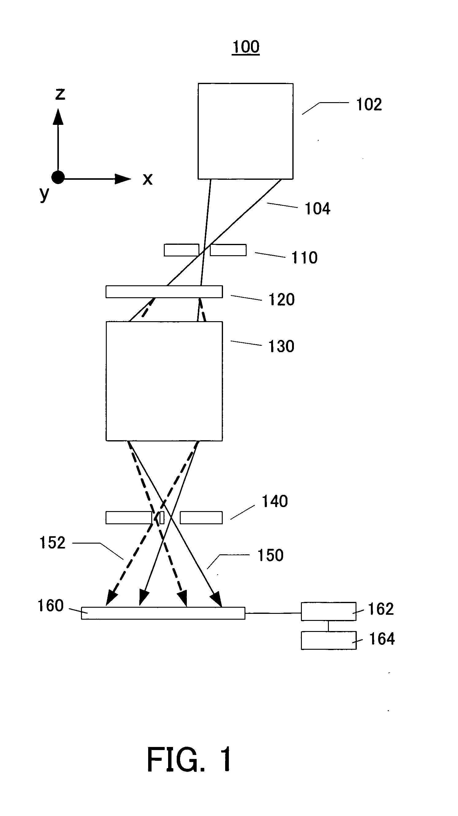
[0026] A description will now be given of a phase shift PDI 100 as one illustrative PDI example according to one embodiment of the present invention and its operation. Here, FIG. 1 is an optical-path diagram of the phase shift PDI 100. In FIG. 1, 102 denotes an illumination optical system, and 104 denotes the light exited from the illumination optical system. 110 denotes a first mask. 120 denotes a grating. 130 denotes a target optical system. 140 denotes a second mask. 150 denotes one of diffracted light by the grating, which passes a window 146 in the mask 140. 152 denotes another diffracted light by the grating, which has an order different from the light 150, and generated from a pinhole 142 in the mask 140. 160 denotes a detector, such as a CCD. 162 is a controller connected to the detector 160. 164 is a memory.

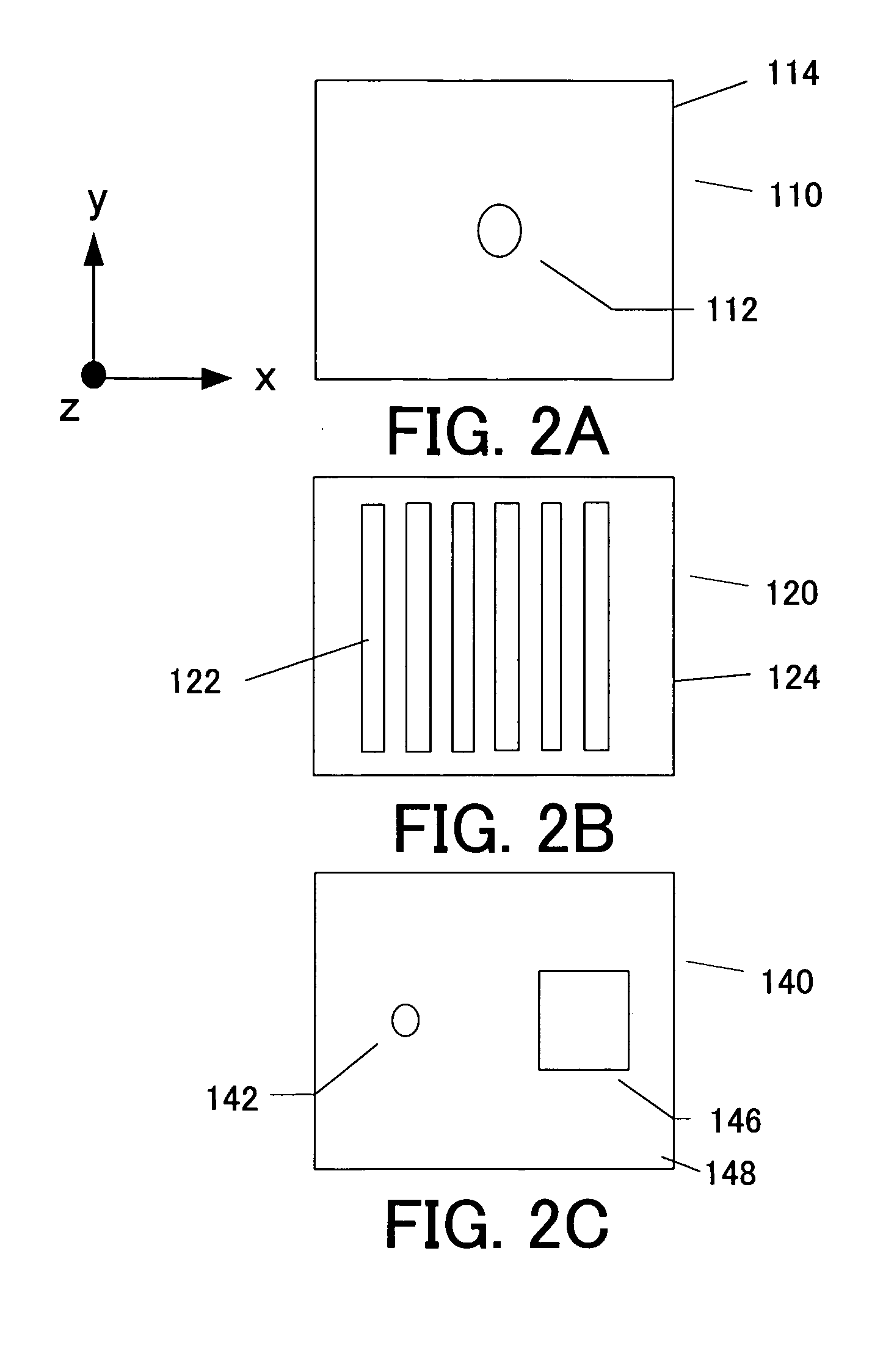
[0027]FIGS. 2A to 2C are plane views of the mask 110, the grating 120 and the mask 140. The mask 110 has a pinhole 112 as an opening and a light-shielding part 114. The...


PUM

PropertyMeasurementUnit
wavelengthaaaaaaaaaa

Abstract

A point diffraction interferometer measures optical performance of a target optical system based on a light intensity distribution of an interference fringe through an interference between a wave front that passes the target optical system and a reference wave front generated from a pinhole, wherein the pinhole satisfies 1.05≦ellipticity≦1.16, where the ellipticity is defined as a diameter of a pinhole in a direction perpendicular to a linear polarization direction of light incident upon the pinhole, divided by a diameter of the pinhole in the linear polarization direction.

Description

BACKGROUND OF THE INVENTION [0001] The present invention relates generally to a method and apparatus for measuring the performance of an optical element, and more particularly to a point diffraction interferometer (“PDI”) that uses a wave front generated from a pinhole as a reference spherical wave in measuring a wave front of a projection optical system that transfers a mask pattern onto an object, and an exposure apparatus and method using the PDI. The inventive PDI is suitable, for example, for an apparatus for measuring the optical performance of the projection optical system that uses the soft X-ray or the extreme ultraviolet light (“EUV”) as exposure light. [0002] A reduction projection exposure apparatus has been conventionally employed which uses a projection optical system to project a circuit pattern of a mask (reticle) onto a wafer, etc. to transfer the circuit pattern, in manufacturing such a fine semiconductor device as a semiconductor memory and a logic circuit in the ...

Claims


Application Information

Patent Timeline
Patent Type & Authority Applications(United States)
IPC IPC(8): G01B9/02G03F7/20H01L21/027
CPCG03F7/706
Inventor OHKUBO, AKINORI
Owner CANON KK
Why Eureka
Try Eureka