Linear guide device

a guide device and linear technology, applied in the direction of linear bearings, shafts and bearings, bearings, etc., can solve the problems of rail cover being raised or detached, difficult to increase the grinding speed, deterioration in machining efficiency, etc., to shorten the machining time of the rail, facilitate the grinding work at high speed, and simplify the configuration of the grinding surface

Active Publication Date: 2005-09-01
NSK LTD
View PDF4 Cites 9 Cited by
  • Summary
  • Abstract
  • Description
  • Claims
  • Application Information

AI Technical Summary

Benefits of technology

[0018] Thus, according to the first and second aspects of the present invention, the rail side surface configuration is simplified to simplify the configuration of the grinding surface of the form grind stone for grinding the same, and grinding work at high speed is facilitated, shortening the rail machining time and achieving an improvement in the machining efficiency thereof.
[0019] According to the third aspect of the present invention, there is provided, in addition to the above, the following effect: the rail upper surface and the rail cover are bonded to each other by the adhesive tape provided therebetween while being pressurized due to their engagement, and even if the linear guide device is used in an environment where it is exposed to a water-soluble substance such as coolant, it is possible to prevent a deterioration in the adhesion property of the adhesive due to intrusion of the water-soluble substance, and it is possible to prevent, for a long period of time, rising or detachment of the rail cover.
[0020] Further, according to the seventh aspect of the present invention, it is possible to lock the cover stopper leg portions in regions other than the track surface on which the rolling members roll, thus making it possible to arrange the cover stopper at either end of the rail without leaving any dent or flaw on the track surface.

Problems solved by technology

However, in the technique as disclosed in U.S. Pat. No. 5,575,566, a step-like undercut is provided on the top of the rail upper side surface to allow engagement of the rail cover, so that it is necessary to form fine protrusions and recesses on the rail side surface and it is necessary for the form grind stone to be of a configuration with fine protrusions and recesses; to avoid damaging these fine protrusions and recesses during grinding, it is rather difficult to increase the grinding speed, resulting in a deterioration in machining efficiency.
Further, in the technique as disclosed in JP 01-120936 A, the plate-like rail cover is glued to the rail upper surface by adhesive to cover the upper surface of the rail, so that, while effective when used in a dry environment, when used in an environment where it is exposed to a water-soluble substance, such as a coolant cutting liquid for use in a machine tool, the device has a problem in that the aqueous solution permeates the adhesive between the plate-like rail cover and the rail upper surface to thereby deteriorate the adhesion property of the adhesive, resulting in the rail cover being raised or detached.
Further, in the technique as disclosed in U.S. Pat. No. 6,513,976, the cover stoppers are engaged with or screwed to the rail track surface to fix the rail cover covering the rail upper surface, so that a dent or flaw due to the pressurizing force or the screw fastening force is generated on the track surface, with the result that the rolling members are subject to damage at the time of movement of the slider or at the time of re-assembly after dismantling, which may lead to generation of noise, an increase in sliding resistance, etc. during sliding movement of the slider.

Method used


Image

  • Linear guide device
  • Linear guide device
  • Linear guide device

Examples


embodiment 1

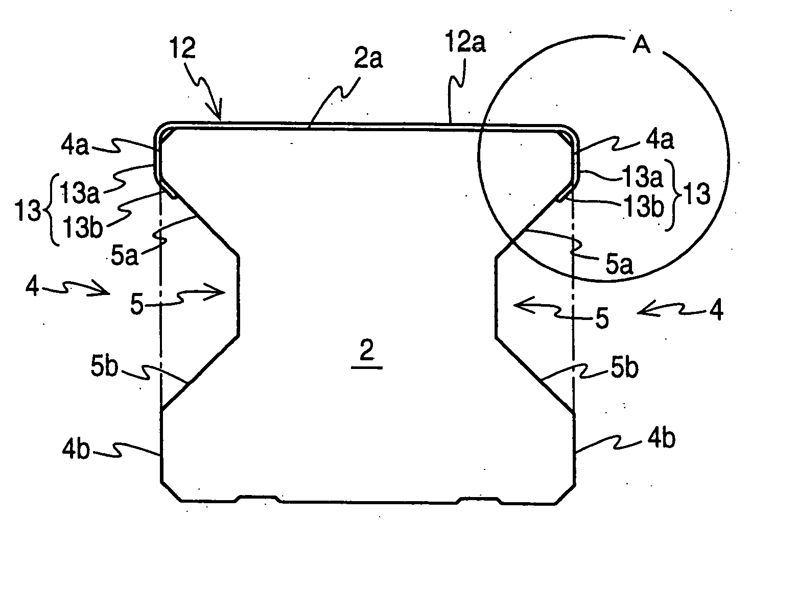
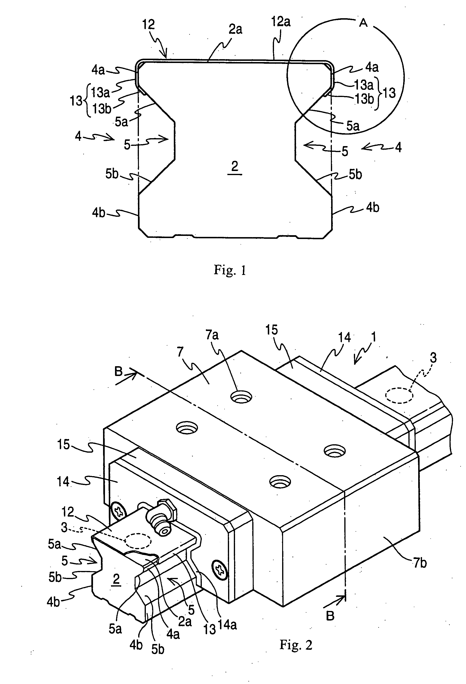
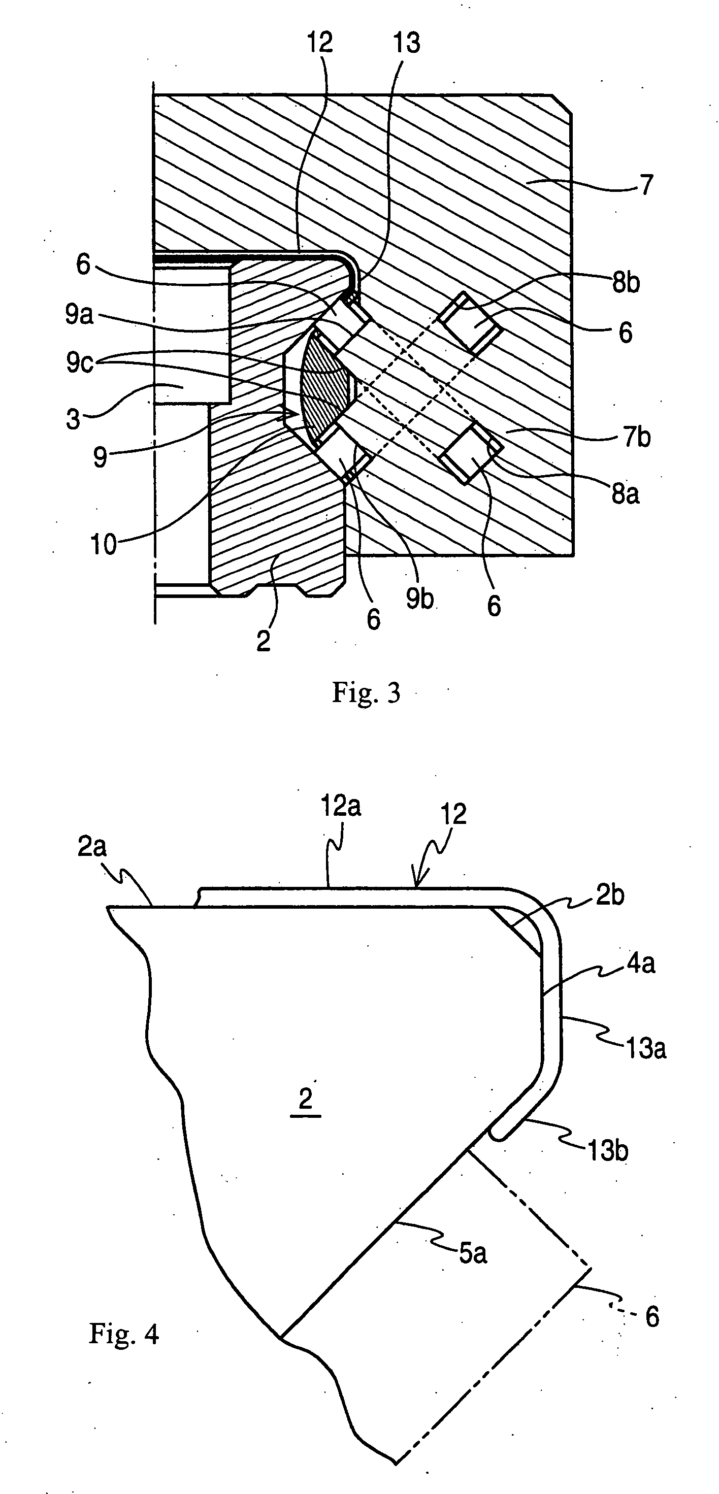
[0066]FIG. 1 is a sectional view of a rail cover and a rail according to Embodiment 1; FIG. 2 is a perspective view of a linear guide device according to Embodiment 1; FIG. 3 is a right-hand-side half sectional view taken along the line B-B of FIG. 2; and FIG. 4 is an enlarged view of portion A of FIG. 1.

[0067] In FIGS. 1, 2, and 3, reference numeral 1 indicates a linear guide device.

[0068] Reference numeral 2 indicates a rail of the linear guide device 1; which is an elongated bar-like member formed of a steel material such as alloy steel and having a substantially I-shaped sectional configuration. In the rail upper surface 2a of the rail, a plurality of stepped bolt holes 3 for fixing the rail 2 to the base or the like of a machine, such as a machine tool, are provided at a predetermined pitch.

[0069] Each side surface 4 of the rail 2 has an upper side surface 4a, with an upper track surface 5a provided under the upper side surface 4a that is a slope gradually diminished downwar...

embodiment 2

[0092]FIG. 5 is a partial enlarged view of a rail and a rail cover according to Embodiment 2.

[0093] The components that are the same as those of Embodiments 1 is indicated by the same reference numerals, and a description thereof will be omitted.

[0094] Reference numeral 21 indicates inclined surfaces serving as engagement surfaces, which are slopes provided under the upper side surfaces 4a on both sides of the rail 2 and gradually diminished downwards from the upper side surfaces 4a in the width direction of the rail 2, with the engagement portions 13b of the rail cover 12 engaging with the engagement surfaces 21 due to the elasticity thereof.

[0095] In this embodiment, the inclined surfaces 21 are provided at the corner portions made by the upper side surfaces 4a and the upper track surfaces 5a of the track recesses 5; the upper side surfaces 4a are vertical surfaces, and the inclined surfaces 21 are inclined by 30 degrees with respect to the vertical direction, and the upper tra...

embodiment 3

[0101]FIG. 6 is a partial enlarged view of a rail and a rail cover according to Embodiment 3.

[0102] The components that are the same as those of Embodiments 1 and 2 are indicated by the same reference numerals, and a description thereof will be omitted.

[0103] The rail 2 and the rail cover 12 of this embodiment are the same as the rail 2 and the rail cover 12 of Embodiment 2 except that the engagement portions 13b of the side edge portions 13 of the rail cover 12 are engaged with the apex portions of corner portions 25 made by the inclined surfaces 21 serving as the engagement surfaces and the upper side surfaces 4a or rounded portions provided at the corner portions 25.

[0104] Thus, the vertical length of the cover side surfaces 13a of the rail cover 12 is formed to be smaller than the length of the cover side surfaces 13a in Embodiment 2.

[0105] As a result, in addition to the effect of Embodiment 2, the engagement portions of the rail cover are engaged with the corner portions m...


PUM


Abstract

In a linear guide device including: a rail having on either side surface thereof a track recess with a track surface formed thereon; a rail cover covering a rail upper surface of the rail; a saddle-like slider moving linearly on the rail; and a rolling member circulating through a connection path provided in the slider and adapted to roll on the track surface of the rail, the rail cover is equipped with a side edge portion having an engagement portion, an upper track surface serving as an engagement surface is provided in a lower portion of an upper side surface of the rail, the engagement surface being a slope gradually diminishing in the rail width direction downwardly from the upper side surface, and an engagement portion of the rail cover is engaged with the engagement surface, whereby it is possible to achieve an increase in the speed of the rail grinding work for allowing engagement of the rail cover covering the rail upper surface of the liner guide device.

Description

BACKGROUND OF THE INVENTION [0001] 1. Field of the Invention [0002] The present invention relates to a linear guide device provided in a guide portion of a machine, e.g., a machine tool, such as a cutting machine or a grinding machine, or an industrial machine, such as a wood working machine, a cutter, or an injection molding machine, and used to linearly move a movable base, such as a table. [0003] 2. Description of the Related Art [0004] In a conventional linear guide device, a saddle-like slider is provided with a connection path, and balls circulating through this connection path are caused to roll on a track surface of a track recess provided on a side surface of a rail so that the slider can move linearly on the rail, and a rail cover whose longitudinal edge portions are bent by an angle smaller than 90 degrees is engaged with an undercut provided on the top of the upper side surfaces on both sides of the rail, preventing intrusion of dust, product chips, etc. by means of seal...

Claims


Application Information

Patent Timeline
Patent Type & Authority Applications(United States)
IPC IPC(8): F16C29/06F16C29/08
CPCF16C29/005F16C29/082F16C29/065
Inventor YAMGUCHI, TOSHIAKIKATO, SOICHIROWEI, XU
Owner NSK LTD
Why Eureka
Try Eureka