Microelectromechannical system

a micro-electromechannical and mechanical technology, applied in the direction of acceleration measurement in multiple dimensions, acceleration measurement using interia forces, speed/acceleration/shock instrument details, etc., can solve the problems of mechanical deformation, deformation of the active part, perceptible measurement errors, etc., to avoid irreversible deformation and/or rupture. , the effect of avoiding the irreversible deformation

Active Publication Date: 2005-09-08
COLIBRYS
View PDF4 Cites 13 Cited by
  • Summary
  • Abstract
  • Description
  • Claims
  • Application Information

AI Technical Summary

Benefits of technology

[0022] Since the active part is capable of moving relatively to the base to which it is fastened, it is isolated from any mechanical constraint that the base could bear, in particular torsion and / or flexion due to it being fastened onto a support. Furthermore, since the movements of the active part are limited by bumper elements, it can be guaranteed thanks to the invention that the fastener or fasteners will not extend beyond their elasticity range, thus avoiding their irreversible deformation and / or rupture.

Problems solved by technology

However, since the distance between the centrifugal mass and the electrode or electrodes of such accelerometers is also very small, the latter are especially sensitive to mechanical deformations, even very mild.
Yet the practically unavoidable constraints exerted on such an accelerometer by it being fastened onto a support, in particular a possible torsion or flexion due to irregularities of the adhesive forces or of the supporting surface, are often sufficient to cause deformations of the active part, inducing perceptible measuring errors, for example because of deformation of the electrodes.
A major disadvantage of these constructions is that their mechanical resistance is limited by the fasteners, resistance.
In fact, beyond a certain acceleration, the displacement of the active part relatively to the rigid frame will provoke an irreversible deformation, or even a rupture of the fasteners, and therefore the destruction of the accelerometer.
Such accelerometers cannot consequently be subjected to considerable accelerations without risking becoming irreversibly damaged.
They are thus particularly sensitive to shocks and cannot be used in certain applications such as for example in ballistics where the accelerations can momentarily reach several tens of thousands times the g acceleration due to the force of gravity.

Method used


Image

  • Microelectromechannical system
  • Microelectromechannical system
  • Microelectromechannical system

Examples


Embodiment Construction

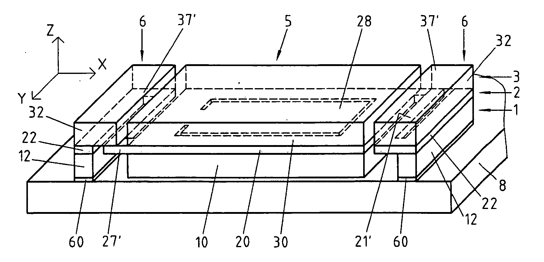
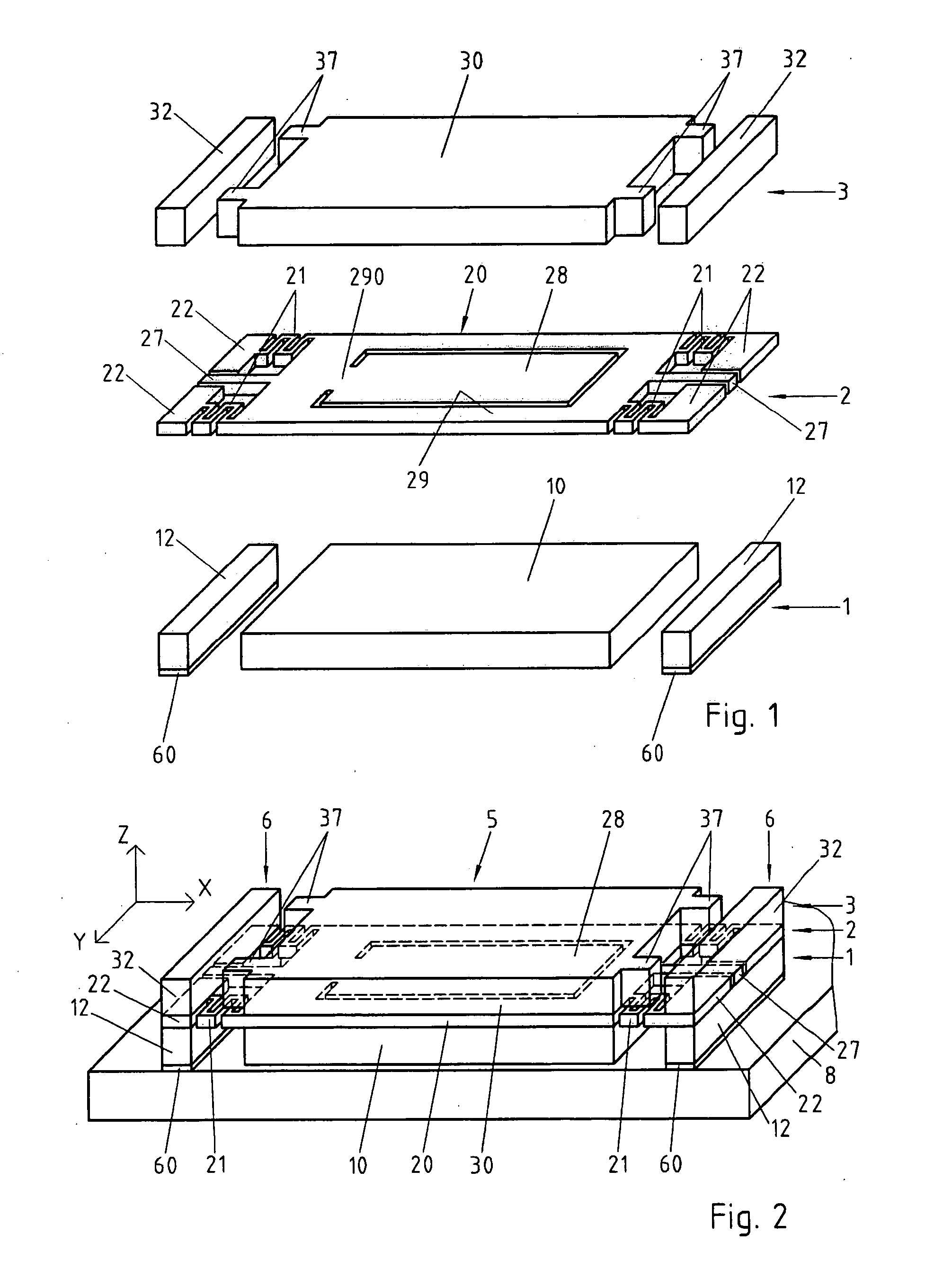
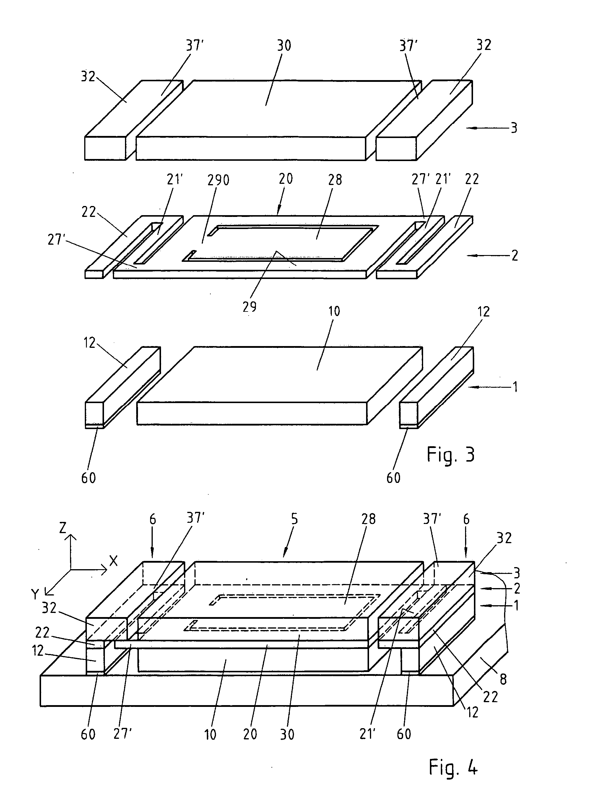
[0028] According to a preferred embodiment illustrated by the FIGS. 1 and 2, the microelectromechanical system (MEMS, Micro Electro Mechanical System) of the invention is an accelerometer comprising three distinct layers 1, 2, 3 of a semiconductor material, for example of silicon. The three layers 1, 2, 3 are preferably electrically isolated from one another by insulating layers (not represented) covering at least partially their contiguous sides and contributing to their mechanical interconnection. These isolating layers are formed for example by oxidation of the corresponding silicon layer's surface and can be structured according to needs by known techniques, for example of photolithography.

[0029] For reasons of simplification, only the structurations of the semiconductor layers 1, 2, 3 are represented in FIGS. 1 and 2.

[0030] The lower layer 1 and the upper layer 3 are structured, for example by photolithography, so as to form a central part 10, resp. 30 and base elements 12 re...


PUM


Abstract

Microelectromechanical system (MEMS) comprising:
    • an active part (5) comprising an electromechanical device (28),
    • at least one base (6) for fastening said microsystem on a support (8),
    • at least one fastener (21, 21′) fastening said active part (5) to said at least one base (6) and allowing a displacement of said active part (5) relatively to said at least one base (6) along an axis (Z) more or less perpendicular to the plane of said support (8) when said microsystem is fastened onto said support (8), bumper elements (27, 27′, 37′) for limiting the amplitude of the displacements of said active part (5) relatively to said at least one base (6) along said perpendicular axis (Z).
The active part (5) being capable of moving relatively to the base (6) to which it is fastened, it is isolated from any mechanical constraint that could be sustained by the base (6), in particular torsion or flexion due to it being fastened onto a support (8). On the other hand, since the movements of the active part (5) are limited by the bumper elements (27, 37, 27′, 37′), it can be guaranteed thanks to the invention that the fastener or fasteners (21, 21′) will not be stretched beyond their elasticity range, thus avoiding their irreversible deformation and/or their rupture.

Description

REFERENCE DATA [0001] This application claims priority of 2004EP-100839 filed on Mar. 2, 2004, the contents whereof are hereby incorporated by reference. FIELD OF THE INVENTION [0002] The present invention concerns a microelectromechanical system (MEMS, Micro Electro Mechanical System). The present invention concerns in particular an accelerometer in the form of a microelectromechanical system. DESCRIPTION OF RELATED ART [0003] Microelectromechanical systems or MEMS are miniaturized systems made from micro- and nanotechnologies derived from microelectronics. They generally integrate mechanical and / or electromechanical elements formed by structuring one or several layers of semiconductor substrate. Among the applications for MEMS are for example accelerometers, optical switching systems, micromotors, etc. The use of MEMS allows a miniaturization of these components as well as an integration of the possible electronic circuits required for controlling them. [0004] An accelerometer gen...

Claims


Application Information

Patent Timeline
Patent Type & Authority Applications(United States)
IPC IPC(8): G01P1/00G01P15/08G01P15/125G01P15/18H01L29/84
CPCG01P15/0802G01P15/18G01P15/125G01P2015/0828
Inventor DUTOIT, BERTRANDBIRLING, SOPHIESTAUFFER, JEAN-MICHELDUPRAZ, YVES
Owner COLIBRYS
Why Eureka
Try Eureka