Phased arrays exploiting geometry phase and methods of creating such arrays

a technology of phased arrays and geometry, applied in direction finders using radio waves, multi-channel direction-finding systems using radio waves, instruments, etc., can solve the problems of large physical footprint of arrays, severe beam distortion over frequency, and process of beamforming over substantial bandwidths, so as to achieve the effect of reducing the coupling of array elements

Inactive Publication Date: 2005-09-08
DAVIS DENNIS WILLARD +2
View PDF8 Cites 170 Cited by
  • Summary
  • Abstract
  • Description
  • Claims
  • Application Information

AI Technical Summary

Benefits of technology

[0038] (h) Provide means to mitigate array element coupling with affecting array pattern.

Problems solved by technology

A number of issues attend the implementation of phased arrays.
At UHF and VHF frequencies, the need for high resolution implies a very large physical footprint for the array.
A secondary issue for arrays is the process of beamforming over substantial bandwidths.
In the wideband case, due to dispersion, the array weights become frequency-dependent functions and to treat them as constants would lead to the occurrence of severe beam distortion over frequency.
Finally, there is the issue of the behavior of the individual array elements.
In the electromagnetic array implementation, wherein the array elements comprise antenna elements, there can be mutual coupling between these elements that can lead to beam pattern distortion.

Method used


Image

  • Phased arrays exploiting geometry phase and methods of creating such arrays
  • Phased arrays exploiting geometry phase and methods of creating such arrays
  • Phased arrays exploiting geometry phase and methods of creating such arrays

Examples


Embodiment Construction

A) Phenomenology

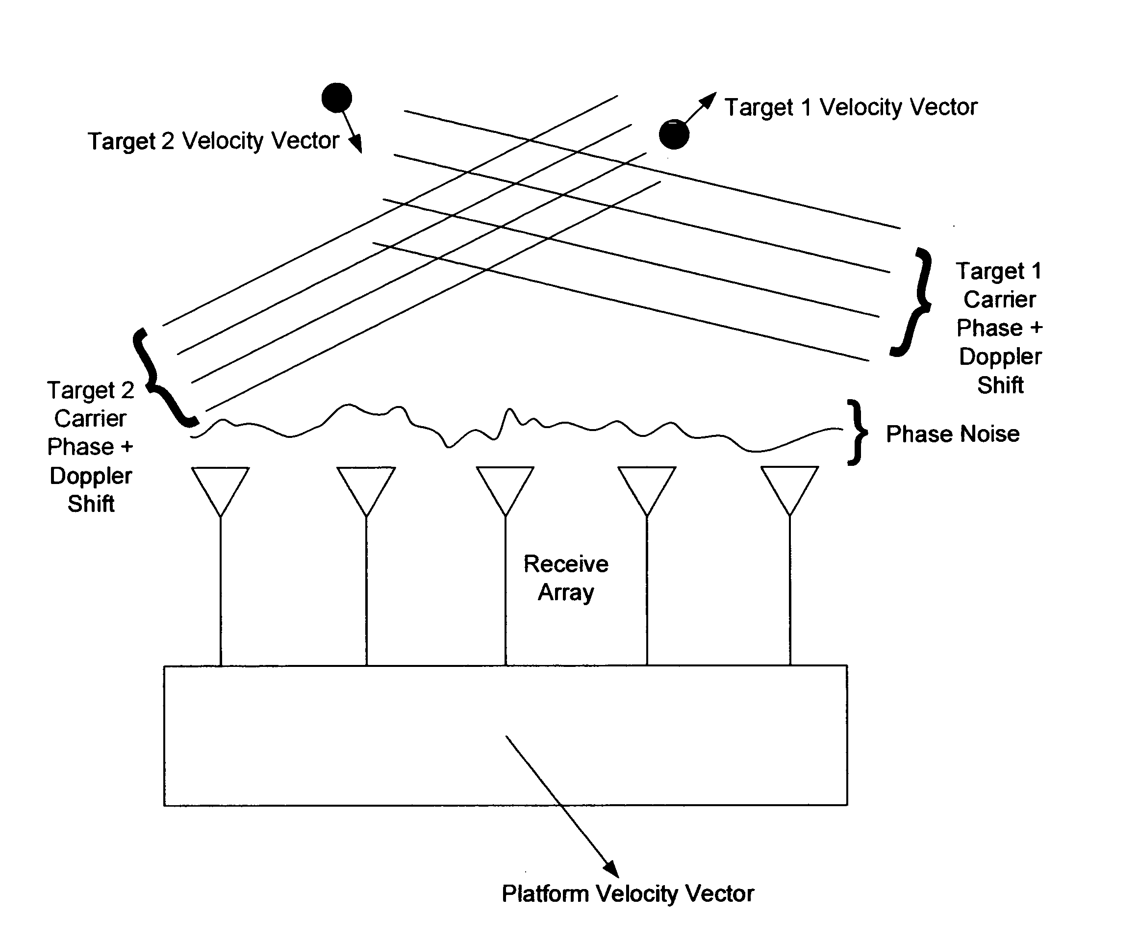
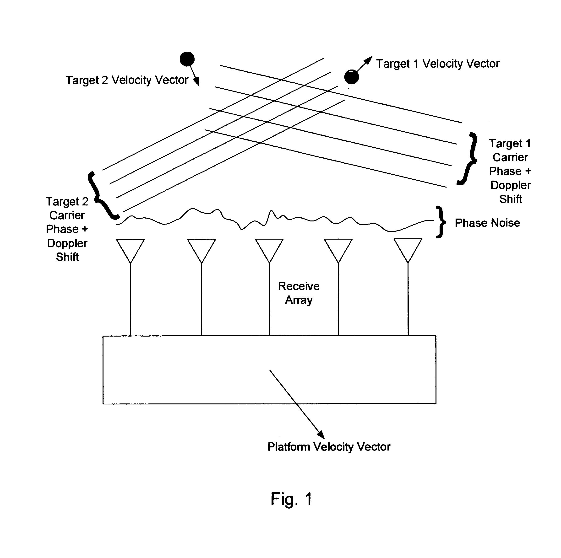
[0085] A description of the underlying phenomenology upon which the present invention is based will be given first in the context of radio frequency (RF) array receivers. Departures from the RF phenomenology in the domain of optics and acoustics will be addressed below. Consider the radar array shown in FIG. 1. The received phase of the signal will change as a function of time due to several factors including motion of the receiver and target (or remote communications transmitter in the communications application), scattering, signal modulation, and receiver noise and error sources. Target translational motion along the radial vector between the receiver and target will impart Doppler shift whereas rotational motion will impart a Doppler spreading of the signal. Changes in the angular position of the target relative to the receiver array boresight will cause angle-of-arrival phase changes, hereafter referred to as geometry phase. The signal can be scattered in either...


PUM


Abstract

In the context of array sensors such as radar, sonar, and communications receiver arrays, the present invention exploits the geometry phase components of radiated wavefronts associated with the signals of interest in order to reduce the bandwidth requirements for DOA and beamforming processing. Additionally, geometry phase is exploited in order to effectively increase the resolution of an array without changing the size of its physical footprint. Other embodiments of the invention include the use of virtual array elements for increase in effective array size.

Description

RELATED DOCUMENTS [0001] This application claims the benefit of U.S. Provisional Application No. 60 / 536,146 filed Jan. 13, 2004 and Document Disclosure Number 527,884 entitled “Miniaturized Phased Arrays and Methods to Fabricate Same,” filed Mar. 15, 2003.BACKGROUND—PRIOR ART [0002] Phased array technology has been in existence for decades and provides an electronic means for aperture synthesis by virtue of electronic control of array element amplitudes and relative phases. As is well known in the prior art, the steady state far field beam pattern of a discrete array of equi-distant emitting elements comprising a phased array, is obtained by the Fourier transform of the complex aperture weights (discrete apodization function) of the array. Hence, the desired beam patterns can be synthesized for both transmission and reception based on the application of appropriate amplifier gains and phase shifter values to each respective element of the array. Further, N−1 beams can be independent...

Claims


Application Information

Patent Timeline
Patent Type & Authority Applications(United States)
IPC IPC(8): G01S1/16G01S3/02G01S13/00
CPCG01S3/54H01Q21/22H01Q3/2629G01S3/74
Inventor DAVIS, DENNIS WILLARDNEUMILLER, PHILLIP DAVIDROMAN, JAIME ROBERTO
Owner DAVIS DENNIS WILLARD
Why Eureka
Try Eureka