Separate network and method for operating a separate network

a technology of separate networks and networks, applied in the direction of dynamo-electric machines, generators/motors, sustainable buildings, etc., can solve the problems of mechanical damage to primary power generators, high technical cost of self-commutated inverters, and relatively strict limit values, etc., to improve the efficiency of an island network

Inactive Publication Date: 2005-09-15
WOBBEN ALOYS
View PDF7 Cites 89 Cited by
  • Summary
  • Abstract
  • Description
  • Claims
  • Application Information

AI Technical Summary

Benefits of technology

[0009] The invention is based on preventing the previously mentioned disadvantages and improving the efficiency of an island network.

Problems solved by technology

However, for fault-free operation, modern electrical devices require the maintenance of relatively strict limit values for voltage and / or frequency fluctuations in the island network.
However, such self-commutated inverters require high technical expense and are correspondingly expensive.
This is also disadvantageous in view of maintenance requirements, fuel consumption, and the loading of the environment with exhaust gases, because even if the internal combustion engine must provide only a fraction of its available power for driving the generator as the network generator, the power frequently equals only 3-5 kW, and the fuel consumption is not insignificant but equals several liters of fuel per hour.
Another problem for known island networks is that so-called “dump loads” must be provided, which consume the excess electrical energy generated by the primary power generator, so that the primary power generator is not set into a free-running operation when loads are turned off, which in turn could lead to mechanical damage to the primary power generator due to an rpm that is too high.
This is especially problematic for wind-power stations as the primary power generators.

Method used


Image

  • Separate network and method for operating a separate network
  • Separate network and method for operating a separate network
  • Separate network and method for operating a separate network

Examples


Embodiment Construction

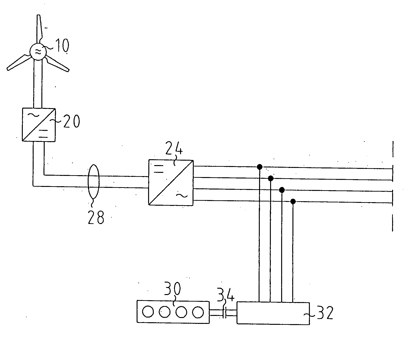
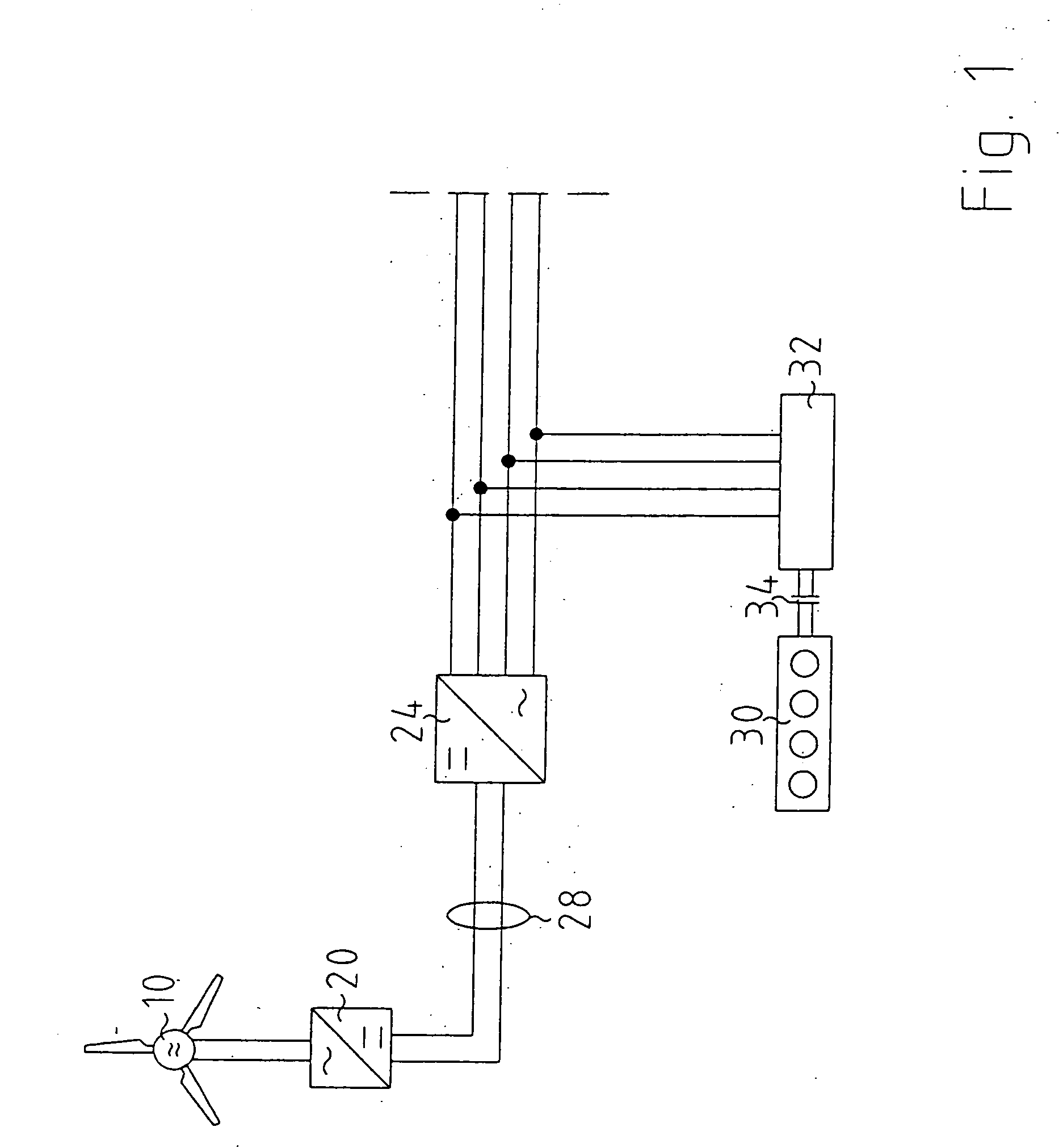
[0025]FIG. 1 shows a wind-power station with a downstream converter consisting of a rectifier 20, by means of which the wind-power station is connected to a dc voltage intermediate circuit 28, as well as an inverter 24 connected to the output of the dc voltage intermediate circuit 28.

[0026] In parallel to the output of the inverter 24, a second synchronous generator 32 is connected, which is connected in turn via an electromagnetic coupling 34 to an internal combustion engine 30. The output lines of the inverter 24 and the second synchronous generator 32 provide the (not shown) load with the required energy.

[0027] In this way, the wind-power station 10 generates the power to be supplied to the load. The energy generated by the wind-power station 10 is rectified by the rectifier 20 and fed into the dc voltage intermediate circuit 28.

[0028] The inverter 24 generates an alternating voltage from the applied dc voltage and feeds it into the island network. Because the inverter 24 is e...


PUM


Abstract

The present invention relates to an isolated network with at least one power generator, which uses renewable energy sources, wherein the power generator is preferably a wind-power station with a first synchronous generator, with a dc voltage intermediate circuit with at least a first rectifier and an inverter, with a second synchronous generator and an internal combustion engine that can be coupled to the second synchronous generator. To realize an isolated network, for which the internal combustion engine can be deactivated completely, as long as the wind-power station generates sufficient power for all connected loads at the highest possible efficiency, a completely controllable wind-power station and an electromagnetic coupling between the second synchronous generator and the internal combustion engine are provided.

Description

BACKGROUND OF THE INVENTION [0001] 1. Field of the Invention [0002] The present invention relates to an electrical island network with at least one power source, which is coupled to a first electric generator. A second generator is further provided, which can be coupled to an internal combustion engine. In such island networks, the power source, which is connected to the first electric generator, preferably a renewable-energy power generator, such as a wind-power station, hydroelectric power plant, etc. [0003] 2. Description of the Related Art [0004] Island networks are generally known and are used especially for supplying power to areas, which are not connected to a central power-supply network but in which renewable energy sources, such as wind and / or sun and / or water power, and the like, are available. These areas referred to herein as an island can be an island in the ocean, or other isolated locations for example, a remote or hard-to-reach areas with isolation in terms of size,...

Claims


Application Information

Patent Timeline
Patent Type & Authority Applications(United States)
IPC IPC(8): H02J3/40H02J7/34H02J9/08
CPCH02J3/40H02J7/34Y02E10/766Y02B10/72Y02E10/763H02J9/08H02J2300/40Y02B10/70Y02E10/76H02J3/38
Inventor WOBBEN, ALOYS
Owner WOBBEN ALOYS
Why Eureka
Try Eureka