
Low cost hardware manufactured from conductive loaded resin-based materials

Inactive Publication Date: 2005-09-15
INTEGRAL TECHNOLOGY INC
View PDF9 Cites 9 Cited by
  • Summary
  • Abstract
  • Description
  • Claims
  • Application Information

AI Technical Summary

Benefits of technology

[0011] A further object of the present invention is to provide an effective hardware fastener having excellent electrical conductivity.
[0012] A further object of the present invention is to provide an effective hardware fastener having excellent thermal conductivity.
[0013] A further object of the present invention is to provide an effective hardware fastener that is non-corrosive.
[0014] A further object of the present invention is to provide an effective hardware fastener that is low in weight.

Problems solved by technology

Such operations require expensive tooling that is worn away during cutting or shaping of the metal.

Method used


Image

  • Low cost hardware manufactured from conductive loaded resin-based materials
  • Low cost hardware manufactured from conductive loaded resin-based materials
  • Low cost hardware manufactured from conductive loaded resin-based materials

Examples


embodiment 10

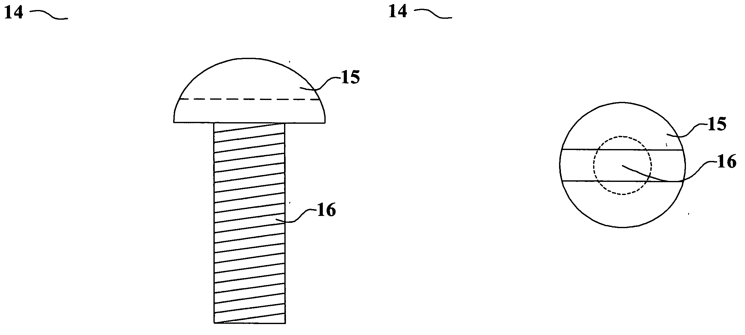
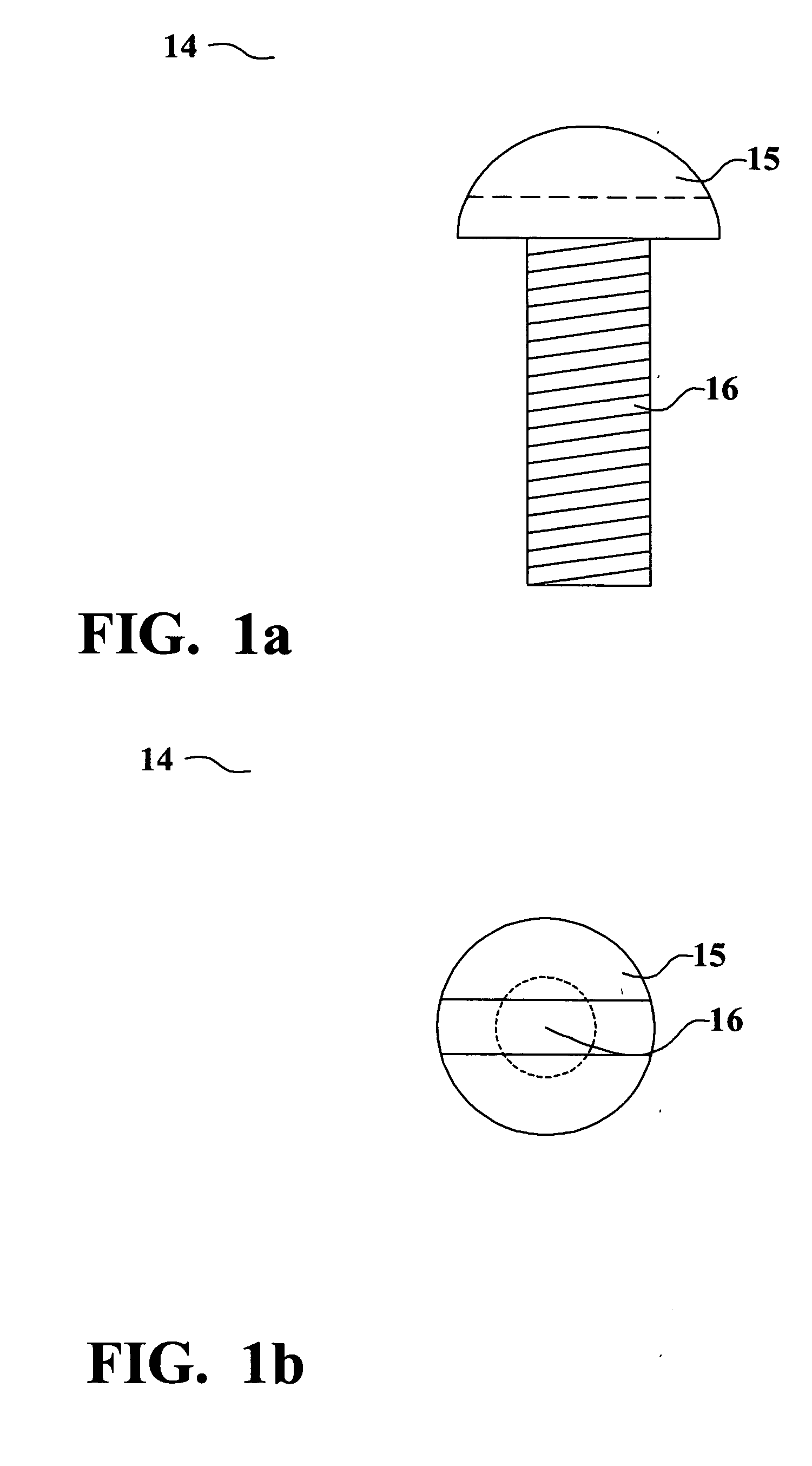
[0054] Referring now to FIGS. 1a and 1b, a first preferred embodiment of the present invention is illustrated. A hardware fastener device formed of the conductive loaded resin-based material is shown. Several important features of the present invention are shown and discussed below. The first preferred embodiment 10 of the present invention shows a very low cost screw 14 device formed of the conductive loaded resin-based material. The novel screw device 14 combines the material advantages of a plastic screw, such as non-corrosiveness, low weight, ease of manufacture, with the material advantages of a metal screw, such as electrical and thermal conductivity. FIG. 1a shows an exemplary side view, while FIG. 1b shows a top view. The screw header 15 and / or the shaft 16 comprises the conductive loaded resin-based material. In the preferred case, both header 15 and shaft 16 comprise conductive loaded resin-based material.

[0055] The screw device 14 comprises a screw head 15 and a screw sha...

first embodiment

[0058] The novel nut device 18 provides threading capable of mating to the threading of the screw device 14 of the In this application, the nut device 18 provides a second end header such that the combined screw 14 and nut 18 is capable of fastening. In one embodiment, the nut device 18 is formed by injection molding. The nut body, including threading, is easily formed in a single molding step. In another embodiment, the nut device 18 is formed by extrusion. Additional machining steps, such as turning or grinding, are performed in some embodiments to form fine detail or ultra-precise features. A non-corrosive nut device 18 is formed by selecting a non-corrosive conductive loading material. In one embodiment, non-corrosive stainless steel fiber is selected as the conductive loading material.

[0059] Referring now to FIGS. 8a and 8b, a third preferred embodiment of the present invention is illustrated. A hardware bolt device 20 formed of the conductive loaded resin-based material is sh...


PUM

PropertyMeasurementUnit
Fractionaaaaaaaaaa
Fractionaaaaaaaaaa
Lengthaaaaaaaaaa

Abstract

Hardware fastener devices are formed of a conductive loaded resin-based material. The conductive loaded resin-based material comprises micron conductive powder(s), conductive fiber(s), or a combination of conductive powder and conductive fibers in a base resin host. The percentage by weight of the conductive powder(s), conductive fiber(s), or a combination thereof is between about 20% and 50% of the weight of the conductive loaded resin-based material. The micron conductive powders are formed from non-metals, such as carbon, graphite, that may also be metallic plated, or the like, or from metals such as stainless steel, nickel, copper, silver, that may also be metallic plated, or the like, or from a combination of non-metal, plated, or in combination with, metal powders. The micron conductor fibers preferably are of nickel plated carbon fiber, stainless steel fiber, copper fiber, silver fiber, aluminum fiber, or the like.

Description

RELATED PATENT APPLICATIONS [0001] This patent application is related to U.S. patent application INT04-008B, Ser. No. ______, and filed on ______, which is herein incorporated by reference in its entirety. [0002] This patent application claims priority to the U.S. Provisional Patent Application Ser. No. 60 / 569,513 filed on May 6, 2004, which is herein incorporated by reference in its entirety. [0003] This patent application is a Continuation-in-Part of INT01-002CIPC, filed as U.S. patent application Ser. No. 10 / 877,092, filed on Jun. 25, 2004, which is a Continuation of INT01-002CIP, filed as U.S. patent application Ser. No. 10 / 309,429, filed on Dec. 4, 2002, now issued as U.S. Pat. No. 6,870,516, also incorporated by reference in its entirety, which is a Continuation-in-Part application of docket number INT01-002, filed as U.S. patent application Ser. No. 10 / 075,778, filed on Feb. 14, 2002, now issued as U.S. Pat. No. 6,741,221, which claimed priority to U.S. Provisional Patent App...

Claims


Application Information

Patent Timeline
IPC IPC(8): B29C45/00G06K19/077H01Q1/12H01Q1/24H01Q1/32H01Q1/36H01Q1/38H01Q1/40H01Q9/04H01Q9/16H01Q9/30H01Q21/00H05K1/09H05K3/10
CPCB29C45/0001H05K2203/0113B29K2995/0005B29L2031/3456G06K19/07749H01Q1/1271H01Q1/36H01Q1/38H01Q1/40H01Q9/0407H01Q9/16H01Q9/30H05K1/095H05K3/101H05K3/107H05K2201/0281H05K2201/09118B29C45/0013Y10T292/03
Inventor AISENBREY, THOMAS
Owner INTEGRAL TECHNOLOGY INC
Learn More