Thin-film solar cell

A technology for solar cells and thin films, applied in the field of solar cells, can solve the problems of limited development, low service life, large resistance of transparent conductive films, etc., and achieve the effects of reducing production costs, improving service life, and excellent electrical conductivity.

Active Publication Date: 2014-04-23
ZHANGJIAGANG KANGDE XIN OPTRONICS MATERIAL
View PDF6 Cites 0 Cited by
  • Summary
  • Abstract
  • Description
  • Claims
  • Application Information

AI Technical Summary

Problems solved by technology

However, at present, the conversion efficiency of flexible solar cells is only about 10%, and the development is greatly restricted. This is mainly due to the following two reasons: first, the transparent conductive layer on the surface of flexible solar cells will reflect sunlight, making part of the sun The loss of light energy. At present, most of the solar panels are blue, indicating that the solar panels cannot absorb the blue part of sunlight, resulting in the loss of part of the photoelectric conversion effect of blue light.
Second, the high resistance of the transparent conductive film will also reduce the conversion efficiency of solar cells
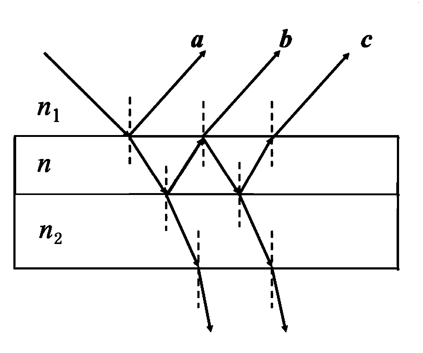
The optical anti-reflection structure designed by Xinmeiwa Industry Co., Ltd., its structure is SiO/SiO/ZrO 2 +TiO 2 /SiO 2 /TiO 2 /SiO 2 , the reflectivity is less than 1% in the visible light range, which has excellent anti-refle

Method used


Image

  • Thin-film solar cell
  • Thin-film solar cell
  • Thin-film solar cell

Examples


Embodiment Construction

[0034] As mentioned in the background technology, the existing thin-film solar cells are limited by the disadvantages of the ITO thin film itself, and there is a problem of low photoelectric conversion efficiency. In order to improve this problem, it is necessary to add an additional anti-reflection film and increase the Thickness can be improved, but the overall thickness of the thin film solar cell will be further increased, and at the same time, the cost will be increased.

[0035] The current high-transmittance and low-resistance multilayer film structure is generally a so-called sandwich structure of metal oxide / conductive layer / metal oxide, as reflected in the patent application number 03116461.7. However, this structure mainly has There are two disadvantages. First, the conductive layer should not be too thick, otherwise it will have a bad impact on the permeability. However, a conductive metal layer that is too thin (such as below 10nm) can easily form an island structu...


PUM

PropertyMeasurementUnit
Thicknessaaaaaaaaaa
Thicknessaaaaaaaaaa
Sheet resistanceaaaaaaaaaa

Abstract

The invention discloses a thin-film solar cell, which comprises a PN junction and transparent conducting films, wherein the PN junction is located above a base material; the transparent conducting films are respectively located at both sides of the PN junction; the two layers of transparent conducting films are used as an upper electrode and a lower electrode of the solar cell; each transparent conducting film comprises a substrate and an antireflection structure attached to the substrate; each antireflection structure comprises two dielectric layers, a conducting metal layer and two antioxidant metal layers, wherein the two dielectric layers are respectively located at the upper outer side and the lower outer side; the conducting metal layer is located in the middle; the two antioxidant metal layers are respectively clamped between the conducting metal layer and the two dielectric layers, wherein the antioxidant metal layers are made of zinc or titanium. By utilizing antireflection structures, under the condition that total thickness is far smaller than the thickness of a traditional ITO (indium tin oxide) film, excellent optical property and electrical property are realized, and moreover, the flexible base material can be selected; through a reel-to-reel magnetron sputtering method, large-scale and large-area production is realized.

Description

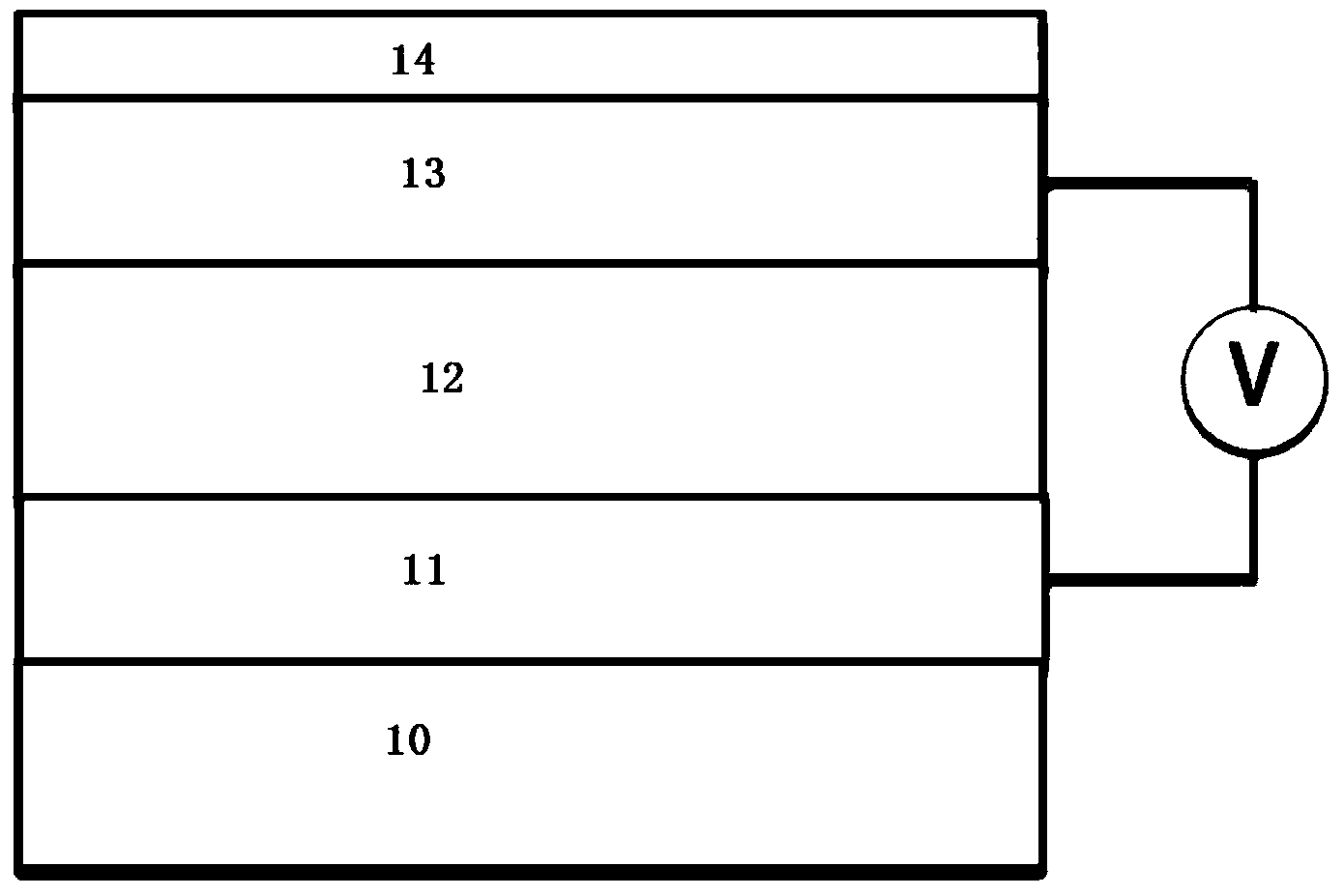
technical field [0001] The invention relates to the field of solar cells, in particular to a thin-film solar cell. Background technique [0002] With the increasing environmental pollution and the depletion of traditional energy, the development and utilization of new energy has become a hot issue in human research. As an inexhaustible green and non-polluting energy source, solar energy is becoming one of the hot spots in the development and utilization of new energy sources. Developed countries are taking the development and utilization of solar energy as the main content of the long-term planning of the energy revolution. [0003] Flexible solar cell is a kind of thin-film solar cell, which has the advantages of lightness and simple process. It can be applied to solar backpacks, solar convertibles, solar flashlights, solar cars and solar airplanes. See figure 1 , figure 1 It is the basic structure of the existing flexible thin film solar cells. The thin-film solar cel...

Claims


Application Information

Patent Timeline
IPC IPC(8): H01L31/0224H01L31/0216
CPCH01L31/02168H01L31/022466Y02E10/50
Inventor 于甄胡坤刘玉婷
Owner ZHANGJIAGANG KANGDE XIN OPTRONICS MATERIAL
Why Eureka
Try Eureka