Projection exposure apparatus, device manufacturing method, and sensor unit

Inactive Publication Date: 2005-09-15
CANON KK
View PDF17 Cites 321 Cited by
  • Summary
  • Abstract
  • Description
  • Claims
  • Application Information

AI Technical Summary

Benefits of technology

[0043] The present invention can detect, at high precision, the wide-a

Problems solved by technology

However, the cost of the apparatus increases when using the F2 excimer laser, EUV light source, and X-ray source.
However, when using the above-described sensor unit in the immersion state, the following problems will occur.
Hence, the light amount cannot be accurately measured by using a total light beam, thus posing a problem.
This problem affects not only the illuminance unevenness sensor unit but also the above-descried calibration sensor unit or the like.
Alternatively, the projection exposure apparatus having a high NA has a factor which degrades the m

Method used


Image

  • Projection exposure apparatus, device manufacturing method, and sensor unit
  • Projection exposure apparatus, device manufacturing method, and sensor unit
  • Projection exposure apparatus, device manufacturing method, and sensor unit

Examples


Example

First Embodiment

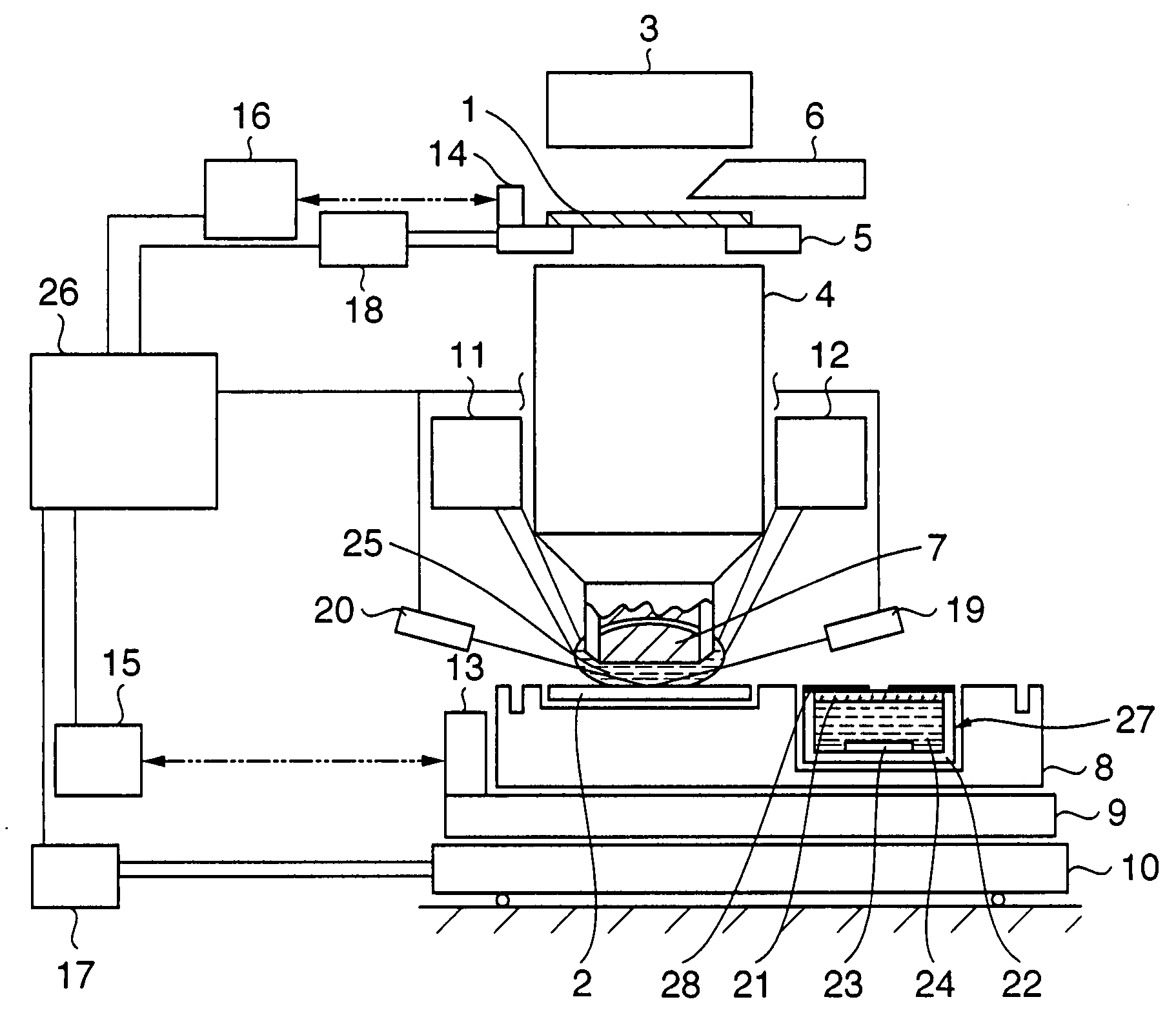
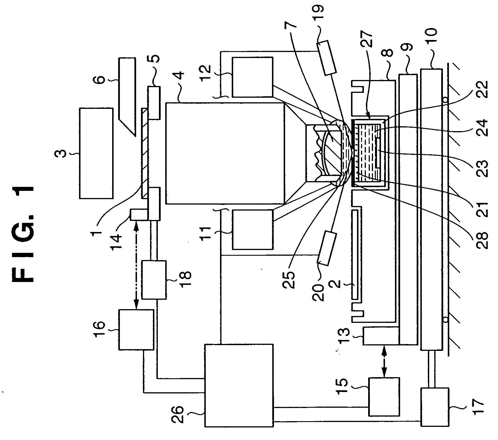
[0069]FIG. 1 is a view showing the schematic arrangement of an immersion-type projection exposure apparatus according to the first embodiment of the present invention. The exposure apparatus shown in FIG. 1 illuminates a reticle 1 by using an illumination optical system 3. A circuit pattern formed on the reticle 1 is projected and transferred onto a wafer 2 coated with a photosensitive agent via a projection optical system 4. The illumination optical system 3 can include a modified illumination forming apparatus, light amount control apparatus, and the like for projecting the circuit pattern of the reticle 1 onto the wafer 2. The reticle 1 is held on the reticle stage 5, and aligned at a predetermined position. The position of the reticle 1 is measured by a laser interferometer 16 using a reference mirror 14 arranged on the reticle stage 5. A driving motor 18 drives the reticle stage 5.

[0070] Information used for aligning the circuit pattern of the reticle 1 and th...

Example

Second Embodiment

[0085]FIG. 6 is a view showing the schematic arrangement of a sensor unit in an immersion-type projection exposure apparatus according to the second embodiment of the present invention. The arrangement and operation of the overall apparatus except for the sensor unit are the same as those in the first embodiment. In FIG. 6, a sealing window 21 on which a light-shielding member 28 having a pattern with a pinhole as in FIG. 3 is formed on a surface by chromium and the like, and a sensor vessel 32 having a circulation ports 32a and 32b separate an internal space from an outer space of a light amount sensor unit 27. A light-receiving element 23 is arranged in the internal space. In this arrangement, an inert liquid 24 is supplied to the internal space of the circulation port 32 to circulate the supplied inert liquid.

[0086] In the outer space, a tank 30 which stores the inert liquid 24, and a liquid feeding pump 31 which supplies the inert liquid 24 in the tank 30 to t...

Example

Third Embodiment

[0091]FIG. 7 is a view showing the schematic arrangement of a sensor unit in an immersion-type projection exposure apparatus according to the third embodiment of the present invention. The arrangement and operation of the overall apparatus except for the sensor unit are the same as those in the first embodiment.

[0092] In the arrangement shown in FIG. 7, a sensor unit 27 includes a light-shielding member 28 having a pattern with a pinhole as in FIG. 3, a sensor vessel 22, a light-receiving element 23, and a coating member 33 (solid material) filled in the sensor vessel 22 to cover the light-receiving element 23. Preferably, the coating member 33 is made of the material which has the refractive index almost equal to or more than that of a liquid 25 used for immersion, has a high transmittance for the exposure light, is hardly degraded by the exposure light, causes no degradation of the characteristic of the light-receiving element 23, and has a resistance to the liqu...


PUM


Abstract

A projection exposure apparatus which has a projection optical system and projects a pattern onto a substrate through the projection optical system is disclosed. This apparatus includes a sensor unit which comprises a light-receiving element for detecting light incident through the projection optical system, a vessel in which the light-receiving element is arranged, and a sealing window which transmits the incident light and seals the vessel. A space between the sealing window and the light-receiving element is filled with a medium having a refractive index greater than 1.

Description

FIELD OF THE INVENTION [0001] The present invention relates to a projection exposure apparatus, device manufacturing method, and sensor unit. BACKGROUND OF THE INVENTION [0002] Along with micropatterning of a semiconductor element, an exposure light source shifts from high-pressure mercury lamp of g-line to a light source of i-line having a shorter wavelength, and further shifts to KrF and ArF excimer lasers having shorter wavelengths. Also, in order to increase a resolution, the NA (numerical aperture) of a projection lens must be increased. Hence, the depth of focus tends to be reduced. As is known well, these relationships are expressed by (resolution)=k1·(λ / NA) (depth of focus)=±k2·λ / NA2 where λ represents the wavelength of light used for exposure, NA represents the NA (numerical aperture) of the projection lens, and k1 and k2 represent coefficients for a process. [0003] Recently, the KrF and ArF excimer lasers with short wavelengths are used. Also, an F2 excimer laser, EUV lig...

Claims


Application Information

Patent Timeline
IPC IPC(8): G03F7/20H01L21/027
CPCG03F7/7085G03F7/70341A63F9/00A63F2250/14G07F17/3297
Inventor AKAMATSU, TAKAHIRO
Owner CANON KK
Why Eureka
Try Eureka