Reflective X-ray microscope and inspection system for examining objects with wavelengths < 100 nm

a x-ray microscope and wavelength technology, applied in the field of refractive x-ray microscopes, can solve the problems of large overall size for achieving adequate lateral magnification, high light loss, and large overall size of objects in reflection, and achieve the effect of small overall siz

Active Publication Date: 2005-09-15
CARL ZEISS SMT GMBH
View PDF17 Cites 19 Cited by
  • Summary
  • Abstract
  • Description
  • Claims
  • Application Information

AI Technical Summary

Benefits of technology

[0023] It is the object of the present invention to avoid the disadvantages of the state of the art, especially those of JP-A-2001116900, and to provide a reflective X-ray microscope that allows the examination of objects for microlithography and has a small overall size. Preferably, the overall size of the X-ray microscope is to be less than 5 m, especially preferably less than 3 m, at a magnification of 10 to 10000×, preferably 300-1000×.

Problems solved by technology

The disadvantage of using Fresnel zone plates in imaging systems with several optical elements in the X-ray-wavelength region is that Fresnel zone plates are transmittive components which lead to high losses of light due to the low transmission in the X-ray wavelength range.
In all X-ray microscopes described in the U.S. patents U.S. Pat. No. 5,144,497, U.S. Pat. No. 5,291,339 and U.S. Pat. No. 5,131,023, the beam path at the object to be examined is designed in a telecentric way, which renders the imaging of objects in reflection more difficult.
A further disadvantage of such systems for the use in examining objects, and especially such used in the area of X-ray lithography, is their large overall size for achieving adequate lateral magnification.
This makes their use in inspection systems for examining masks in EUV projection illumination systems more difficult.
The disadvantage of a system as disclosed by JP-A-2001116900 is that it has a very large overall size when a large lateral magnification is required.

Method used


Image

  • Reflective X-ray microscope and inspection system for examining objects with wavelengths &#x3c; 100 nm
  • Reflective X-ray microscope and inspection system for examining objects with wavelengths &#x3c; 100 nm
  • Reflective X-ray microscope and inspection system for examining objects with wavelengths &#x3c; 100 nm

Examples


Embodiment Construction

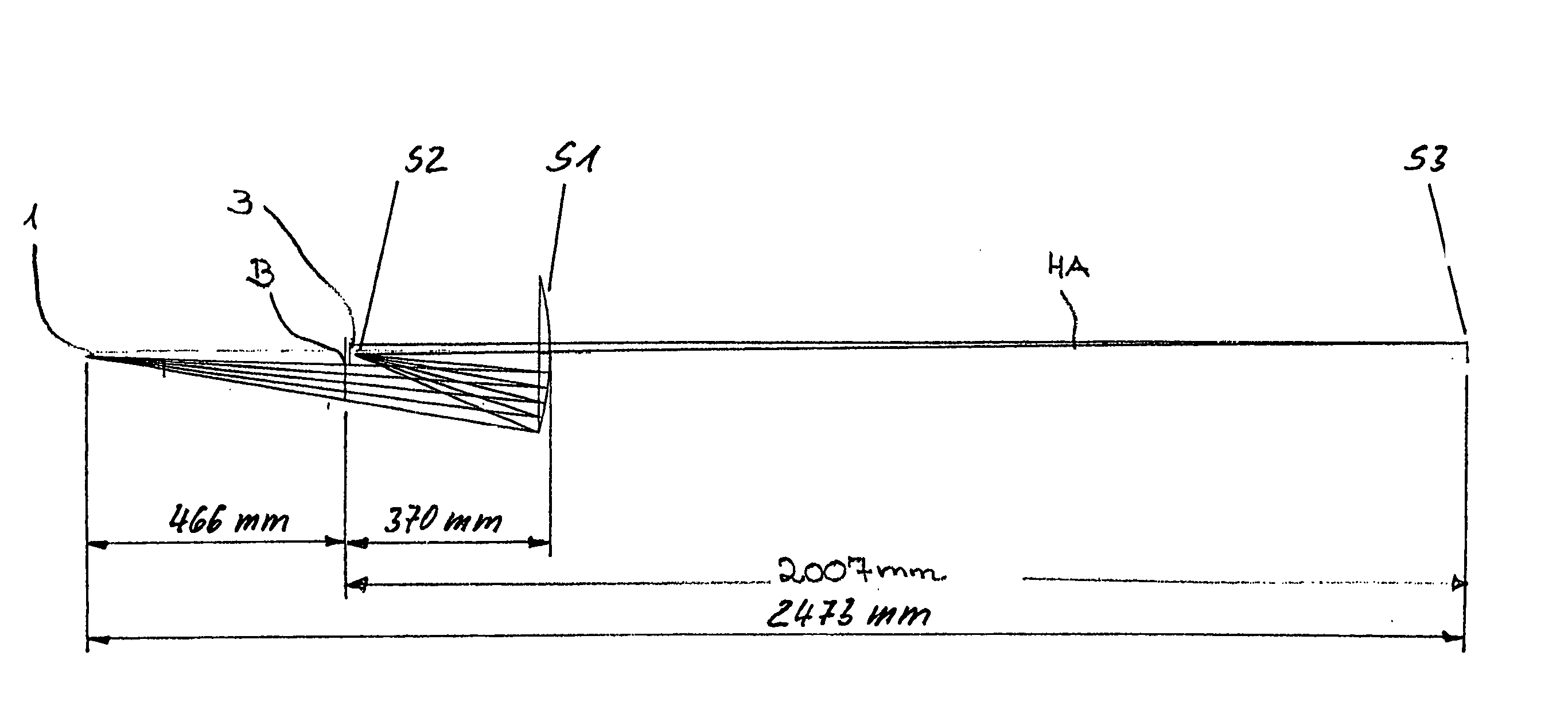
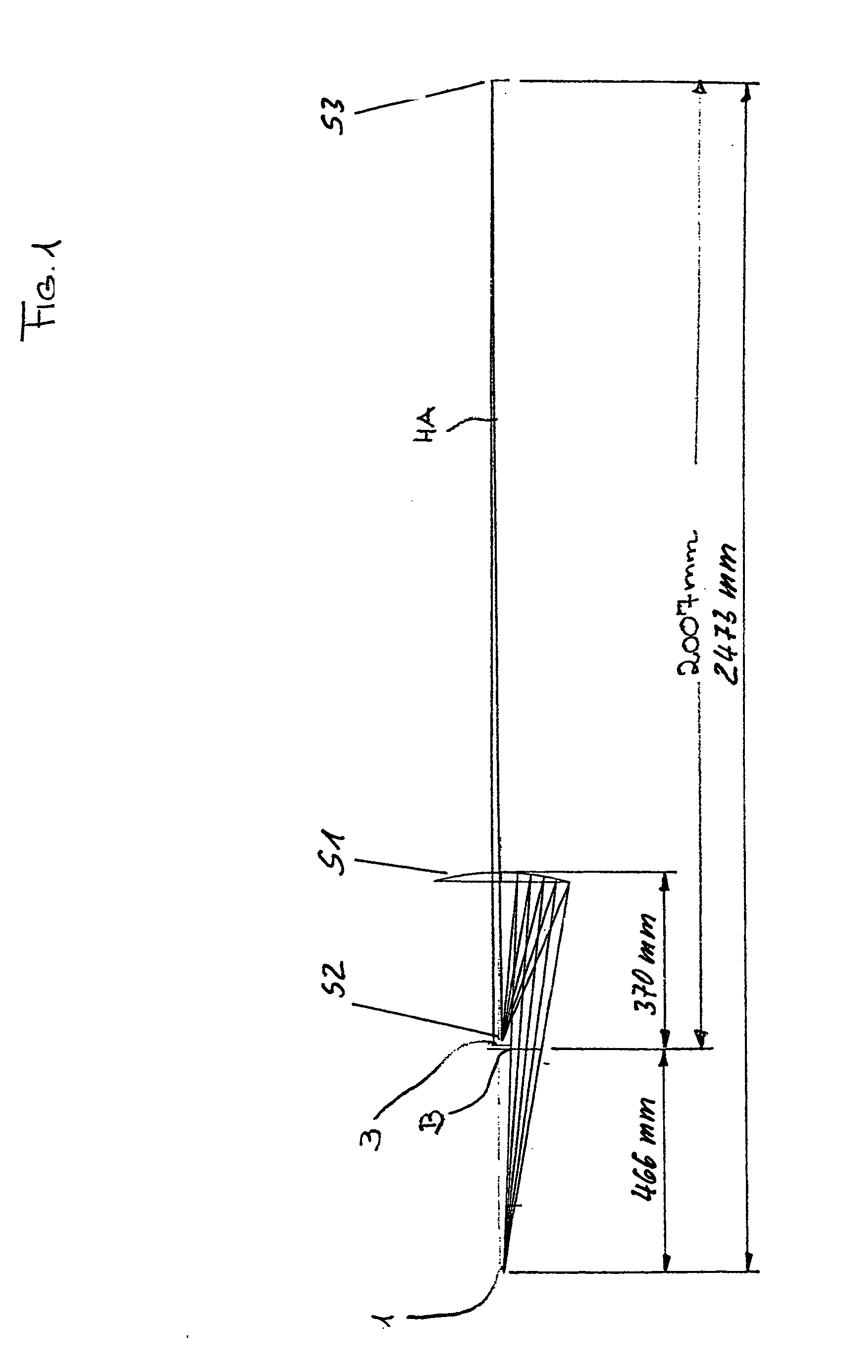
[0108]FIG. 1 shows a first embodiment of an X-ray microscope with a first subsystem comprising a first mirror S1 and a second mirror S2. In the present embodiment, mirror S1 is a concave mirror and second mirror S2 is a convex mirror. Mirrors S1 and S2 are centered with respect to, i.e., centric to, an optical axis HA. A second subsystem comprises a third mirror S3. The third mirror is also arranged centric relative to the optical axis HA. An object is situated in an object plane 1, arranged in a decentered, i.e., off-centered, manner relative to the optical axis HA, and is projected by the X-ray microscope into an image plane 3. The image plane 3 is situated close to the second mirror S2 and an aperture diaphragm B. The aperture diaphragm B is arranged in a decentered fashion relative to the optical axis HA between object plane 1 and first mirror S1.

[0109] The radius of curvature of the first mirror S1 is |R1|=500 mm, the radius of the second mirror S2 is |R2|=3.5 mm and that of t...


PUM

PropertyMeasurementUnit
wavelengthaaaaaaaaaa
wavelengthsaaaaaaaaaa

Abstract

There is provided a reflective X-ray microscope for examining an object in an object plane. The reflective X-ray microscope includes (a) a first subsystem, having a first mirror and a second mirror, disposed in a beam path from the object plane to the image plane, and (b) a second subsystem, having a third mirror, situated downstream of the first subsystem in the beam path. The object is illuminated with radiation having a wavelength <100 nm, and the reflective X-ray microscope projects the object with magnification into an image plane.

Description

CROSS-REFERENCE TO RELATED APPLICATIONS [0001] The present application is a continuation of International Application No. PCT / EP03 / 04803, filed May 8, 2003, which claims priority of (a) German Patent Application No. 102 20 816.6, filed May 10, 2002, and (b) German Patent Application No. 102 20 815.8, filed May 10, 2002.BACKGROUND OF THE INVENTION [0002] 1. Field of the Invention [0003] The invention relates to a reflective X-ray microscope for examining an object in an object plane, with the object being illuminated with radiation of a wavelength ≦100 nm, especially <30 nm, and imaged in an enlarged way in an image plane. Such a reflective X-ray microscope comprises a first subsystem which is arranged in the beam path from the object plane to the image plane and which comprises at least one first optically imaging element, preferably a first mirror. [0004] 2. Description of the Related Art [0005] X-ray microscopes are known from the following applications: [0006] U.S. Pat. No. 5,...

Claims


Application Information

Patent Timeline
Patent Type & Authority Applications(United States)
IPC IPC(8): G03F1/16G21K1/06G21K7/00H01L21/027
CPCG21K7/00B82Y10/00G21K1/062
Inventor MANN, HANS-JURGENDINGER, UDOULRICH, WILHELMREINECKE, WOLFGANGENGEL, THOMASZIBOLD, AXELHARNISCH, WOLFGANGWEDOWSKI, MARCOPAUSCHINGER, DIETER
Owner CARL ZEISS SMT GMBH
Why Eureka
Try Eureka