Method for calculating filter clogging factor and bed-side system

a filter clogging and factor technology, applied in the field of filter clogging factor calculation, method and apparatus for monitoring filter clogging, and bedside system, can solve the problems of increasing the possibility of causing a blood pressure drop, affecting the safety and economic efficiency of the operation, and producing serious hemorrhagic complications, so as to prevent reduce the ease of blood flow. , the effect of preventing the progress of filter clogging

Inactive Publication Date: 2005-09-15
KONINKLIJKE PHILIPS ELECTRONICS NV
View PDF4 Cites 29 Cited by
  • Summary
  • Abstract
  • Description
  • Claims
  • Application Information

AI Technical Summary

Benefits of technology

[0013] According to this method, it is possible to discover filter clogging in an early stage, appropriately adjust the amount of dosage of an anticoagulant without overdosage, change a flow rate setting and thereby prevent the progress of filter clogging. Furthermore, it is also possible to set a flow rate considering back-filtration of each filter by controlling back-filtration.
[0014] In the method for calculating a clogging factor of a filter according to the present invention, it is preferable to calculate a filter clogging factor indicating the reduction in flowing ease of the blood in the filter by using a viscosity of blood. This makes it possible to precisely evaluate a level of clogging indicating the reduction in flowing ease of the blood in the filter.
[0015] In the method for calculating a clogging factor of a filter according to the present invention, a filter clogging factor indicating the reduction in flowing ease of the blood in said filter is calculated by using structure information and / or flow rate information of the filter. This makes it possible to precisely evaluate a level of clogging indicating the reduction in flowing ease of the blood in the filter.
[0020] In the method for calculating a clogging factor of a filter according to the present invention, a filter clogging factor indicating the reduction in ease of filtering of the filter is calculated by using structure information and / or flow rate information of the filter. This makes it possible to precisely evaluate a level of clogging indicating the reduction in ease of filtering of the filter.
[0026] This makes it possible to eliminate the influences of errors included in the correction coefficient in the calculation equation of the filter clogging factor and monitor the filter clogging more precisely irrespective of factors affecting the pressure indices (filter structure, blood purification apparatus, blood purification circuit, flow rate, biometric factor).

Problems solved by technology

For example, when a filter with a large membrane area is used, the capacity of removal of substances may be improved, but the amount of blood retained outside the body (in the filter) increases, which increases the possibility of causing a blood pressure drop, and therefore it is essential to select a filter suited to the physical constitution and clinical conditions of the patient.
Since clogging of filter in this blood purification method may cause problems in terms of safety and economical efficiency, anti-clogging measures by using an anticoagulant or adjusting flow rate, etc., are taken on the medical work front.
Overdosage of this anticoagulant in an attempt to prevent clogging of a filter may not only cause a danger of producing serious hemorrhagic complications (cerebral hemorrhage, etc.) but also raise an economical question because the anticoagulant is expensive.
However, it is difficult that a level of filter clogging is monitored accurately.
Therefore, it has been impossible to precisely evaluate a filter clogging situation or make a comparative analysis of the blood purification method adopted under various conditions (using various filters, blood purification apparatuses, blood purification circuits, flow rate settings, viscosities of blood and liquid waste, etc.) based on pressure indices alone.
However, if filtering pressure measured at one point is used, it is difficult that filter clogging in filter having back-filtration is monitored accurately.

Method used


Image

  • Method for calculating filter clogging factor and bed-side system
  • Method for calculating filter clogging factor and bed-side system
  • Method for calculating filter clogging factor and bed-side system

Examples


Embodiment Construction

)

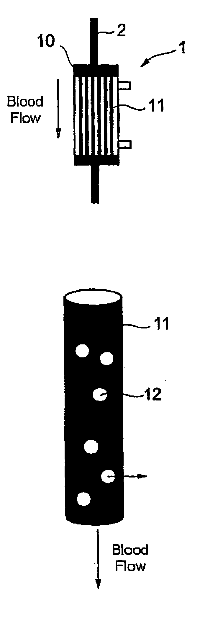
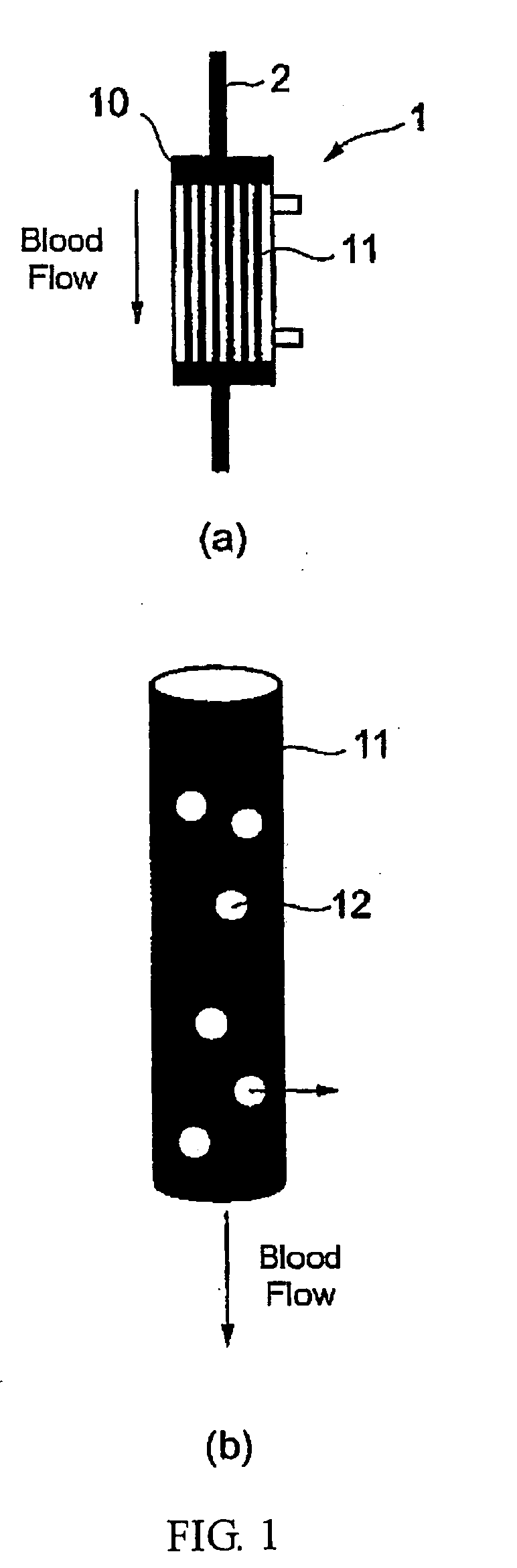
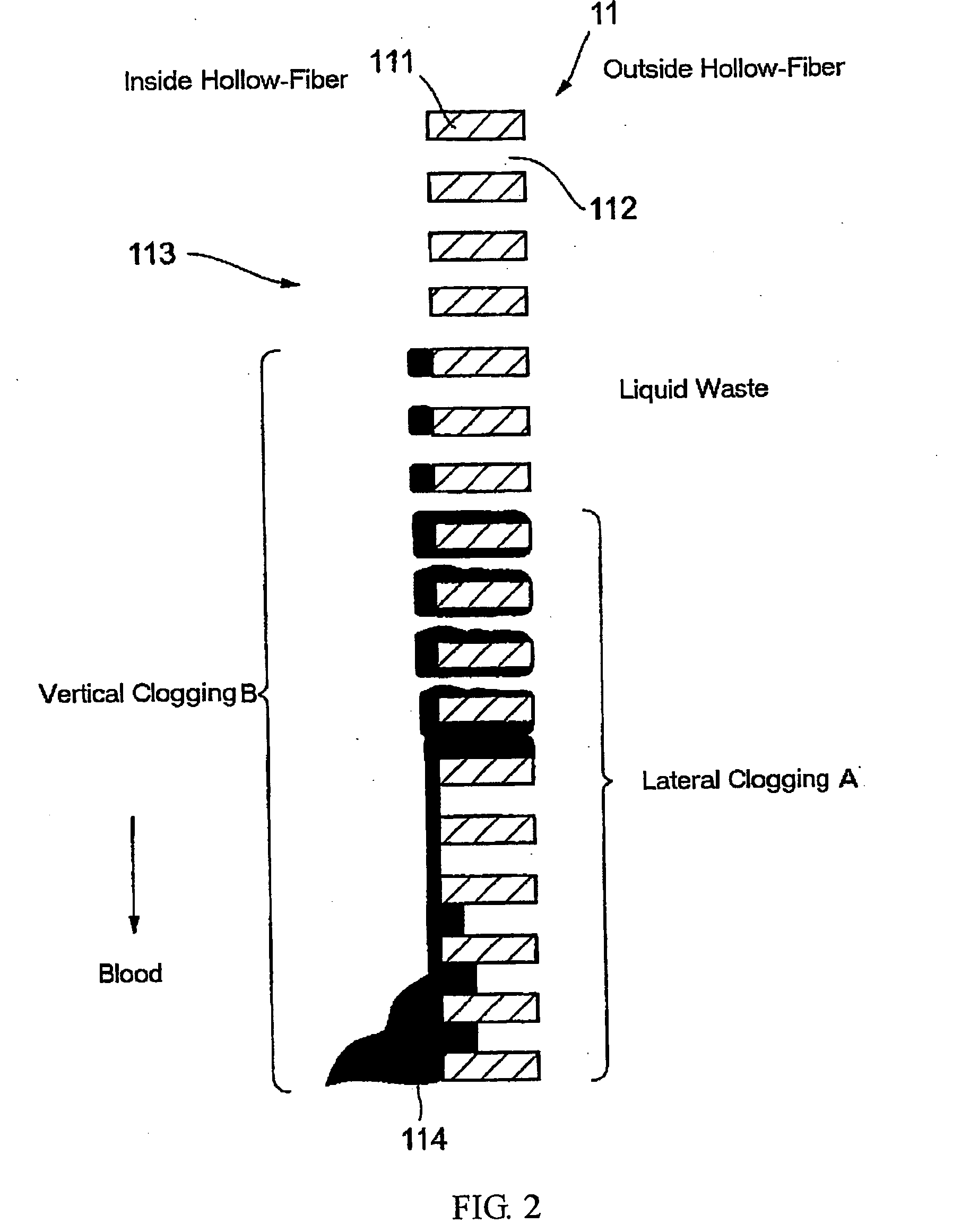
[0043] The present inventors have noticed the fact that there are two modes of filter clogging; (vertical) clogging indicating the reduction in flowing ease of the blood in the filter and (lateral) clogging indicating the reduction in ease of filtering using the filter, and have come up with the present invention by discovering that it is possible to accurately monitor filter clogging by calculating a filter clogging factor on the basis of a relationship between clogging in each mode of clogging and pressure.

[0044] That is, a subject matter of the present invention is to measure at least two pressures selected from the group consisting of a pressure in the blood inflow portion, a pressure in the blood outflow portion, a filtering pressure in the blood inflow portion, and a filtering pressure in the blood outflow portion of the filter and calculate filter clogging factors in vertical direction and lateral direction using the measured pressures. This makes it possible to discover fi...


PUM


Abstract

Method for calculating a clogging factor of a filter composed of hollow-fiber membrane, which has a blood inflow portion 32a and a blood outflow portion 32b, by passing a blood, the method including the steps of measuring at least two pressure selected from the group consisting of a pressure (Pa) in said blood inflow portion, a pressure (Pv) in said blood outflow portion, a filtering pressure (Pf1) in said blood inflow portion, and a filtering pressure (Pf2) in said blood outflow portion and calculating a filter clogging factor in vertical direction and / or a filter clogging factor in lateral direction using at least two of the measured pressures, flow rate information, biometric information (viscosity information and so on), and structure information.

Description

BACKGROUOND OF THE INVENTION [0001] 1. Field of the Invention [0002] The present invention relates to a method for calculating filter clogging factor, method and apparatus for monitoring filter clogging, and bed-side system provided with an apparatus for monitoring a filter clogging factor, which are used in the blood purification method. [0003] 2. Description of Related Art [0004] A blood purification method can be roughly classified into two types. One is a type that removes substances in the blood through removal to liquid waste (dialysis, filtering) or adsorption into membranes when the blood flows in hollow-fibers of a filter, and hemodialysis, hemofiltering, hemodiafiltering, plasma exchange, double filtering plasmapheresis, plasmapheresis are some examples of this type. The other is a type that removes substances in the blood through adsorption into an adsorbent in a filter when the blood passes through the adsorbent (cloth, bead, etc.), and blood adsorption is an example of ...

Claims


Application Information

Patent Timeline
Patent Type & Authority Applications(United States)
IPC IPC(8): A61M1/16A61M1/36B01D61/22B01D61/32B01D65/10
CPCA61M1/16A61M1/3639A61M1/3672A61M2205/3331A61M2205/707A61M1/3609B01D61/22B01D61/32B01D65/10A61M1/1627A61M2205/7563A61M1/34A61M2205/3334A61M1/3403A61M1/341A61M1/3607B01D65/109
Inventor KURODA, YASUHIROOKAHISA, TOSHIYAOHNISHI, YOSHIAKI
Owner KONINKLIJKE PHILIPS ELECTRONICS NV
Why Eureka
Try Eureka