
Weight function generating method, reference signal generating method, transmission signal generating apparatus, signal processing apparatus and antenna

a signal processing and function generating technology, applied in the direction of using reradiation, digital technique network, instruments, etc., can solve the problems of large loss, large aperture plane distribution of antennas, and insufficient reduction of side lobe level, so as to improve the characteristics along the time axis and reduce the loss of signal processing

Active Publication Date: 2005-09-15
KK TOSHIBA
View PDF15 Cites 22 Cited by
  • Summary
  • Abstract
  • Description
  • Claims
  • Application Information

AI Technical Summary

Benefits of technology

[0008] An object of the invention is to improve the characteristics along the time axis, and to provide a weight function generating method, a reference signal generating method, a transmission signal generating apparatus, a signal processing apparatus and an antenna unit to reduce the signal processing loss and realize an ideal signal processing.
[0011] According to a third aspect of the present invention, there is provided a method of generating a reference signal in frequency domain to secure correlation with an input signal by multiplying a basic signal by a predetermined weight function in time domain, the method comprising: transforming the basic signal from the time domain to the frequency domain; and multiplying the basic signal by a window function (a Hamming window, a Hanning window, a Gaussian window, a BlackmanHarris window, a FlatTop window, etc.) in frequency domain thereby to generate the reference signal in frequency domain.
[0016] According to a eighth aspect of the present invention, there is provided a method of generating a weight function for attaching a characteristic based on a window function (a Hamming window, a Hanning window, a Gaussian window, a BlackmanHarris window, a FlatTop window, etc.) to an input signal in time domain, the method comprising: extending a waveform of the window function at a peak amplitude point to generate a waveform corresponding to a unit time of the input signal, thereby generating the weight function.
[0021] According to a thirteenth aspect of the present invention, there is provided a signal processing apparatus for analyzing a signal by Fourier transform of a signal to be analyzed into a distribution on a frequency axis, the apparatus comprising: obtaining means for obtaining a weight function to suppress a spurious leak of the signal to be analyzed which is generated by extending a waveform of a window function (a Hamming window, a Hanning window, a Gaussian window, a BlackmanHarris window, a FlatTop window, etc.) at a peak amplitude point and generating a waveform corresponding to a unit time of the signal to be analyzed; and a multiplier which multiplies the weight function and the signal to be analyzed in time domain before Fourier transform.

Problems solved by technology

This processing in time domain, however, cannot suppress the side lobe in frequency domain, and the signal processing loss poses a great problem.
Under the circumstances, however, the aperture plane distribution of the antenna is generally accompanied by a large loss, and the side lobe level is not sufficiently reduced.
Further, the spurious frequency component of the transmission signal often cannot be suppressed sufficiently.
Furthermore, in the correlation processing in the pulse compression, etc., the unnecessary wave components (range side lobe) generated in the signal processing often mask a minute input signal.

Method used


Image

  • Weight function generating method, reference signal generating method, transmission signal generating apparatus, signal processing apparatus and antenna
  • Weight function generating method, reference signal generating method, transmission signal generating apparatus, signal processing apparatus and antenna
  • Weight function generating method, reference signal generating method, transmission signal generating apparatus, signal processing apparatus and antenna

Examples


first embodiment

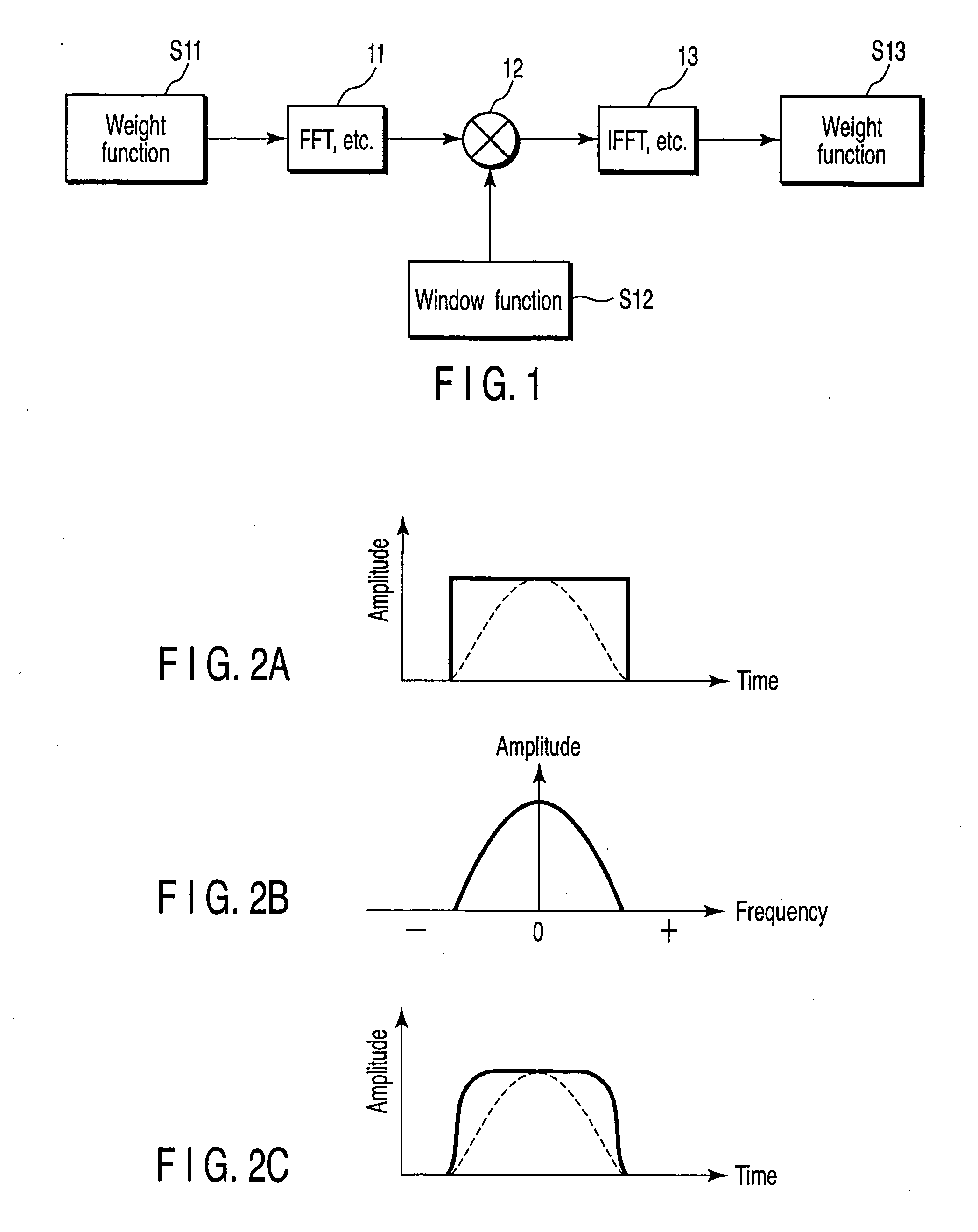
[0043]FIG. 1 is a block diagram showing a processing configuration to generate a weight function according to a first embodiment of the invention, and FIG. 1 a waveform diagram for the processing thereof. In FIG. 1, assume that a weight function in time domain is selected in the range of the rectangular waveform shown in FIG. 2A. Also assume that the conventional window functions (Hamming window, Hanning window, Gaussian window, BlackmanHarris window, FlatTop window, etc.) are applied as shown by a dotted line in this range of the weight function. In the area ratio represented by time multiplied by amplitude, the worst loss of 50% develops. According to this invention, the rectangular wave S11 constituting the basis of FIG. 2A is transformed into the frequency domain by an FFT (fast Fourier transform) 11, and multiplied by the window function (BlackmanHarris window, etc.) S12 generated on frequency axis shown in FIG. 2B in a multiplier 12, after which the time domain is restored by ...

second embodiment

[0045] As described above, the signal processing such as FFT is widely used to multiply the window function with the aim of reducing the spurious leak. Window functions such as the Hamming window, the Hanning window, the Gaussian window, the BlackmanHarris window, the FlatTop window, etc. are known.

[0046] The multiplication process using these window functions, however, is accompanied by a large signal loss, and about one half of the signal is lost. As a method to reduce the signal loss while at the same time suppressing the unnecessary spurious leak, according to the first embodiment of the invention, the weight function based on the window function is generated by transforming the weight function in time domain is transformed into the frequency domain, and the multiplied by the window function on frequency axis, after which the signal in time domain is restored. In this method, the waveform of the window function becomes so steep at the rise and fall of the weight function that t...

third embodiment

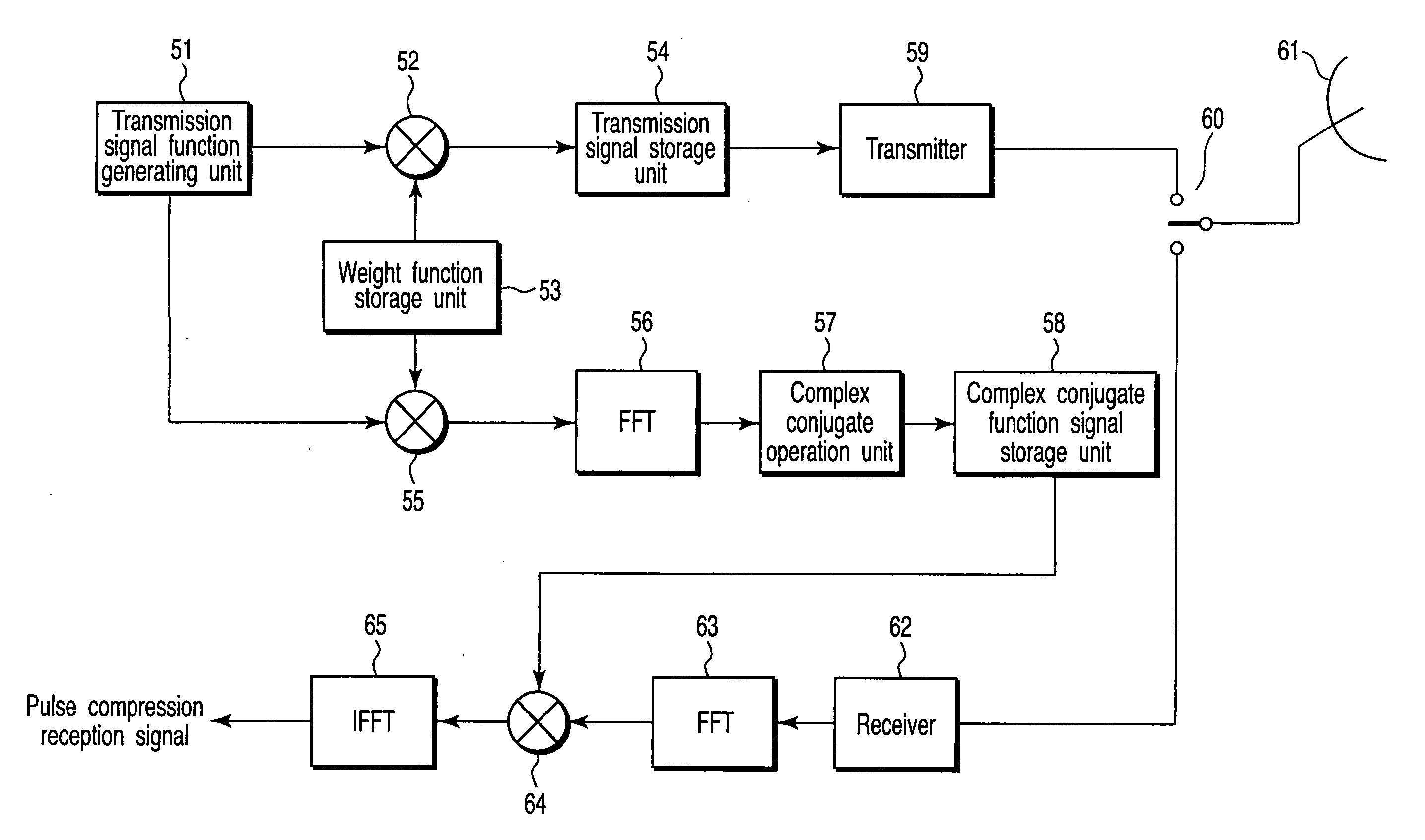
[0054]FIG. 6 is a block diagram showing a processing configuration to generate a reference signal for correlation processing according to a third embodiment of the invention. A reference signal S21 is sent to a multiplier 21 and multiplied by a weight function S22. The weight function S22 is generated by the method according to the first or second embodiment. The reference signal S21′ multiplied by the weight function S22 constitutes a reference signal S23 in time domain. The reference signal 23 thus generated is multiplied by the weight function generated in the first embodiment, and therefore the signal processing loss and the range side lobe are reduced, thereby producing an ideal waveform as a reference signal.


PUM


Abstract

A rectangular wave for determining a range of a weight function is transformed to frequency domain by an FFT or the like, and after being multiplied by a window function (BlackmanHarris window function, for example) generated on a frequency axis by a multiplier, the frequency domain is transformed again to the time domain by an IFFT or the like thereby to generate a weight function.

Description

CROSS-REFERENCE TO RELATED APPLICATIONS [0001] This application is based upon and claims the benefit of priority from prior Japanese Patent Application No. 2004-068911, filed Mar. 11, 2004, the entire contents of which are incorporated herein by reference. BACKGROUND OF THE INVENTION [0002] 1. Field of the Invention [0003] The present invention relates to a technique for preprocessing of a weight function, etc. attaching a predetermined characteristic to a waveform signal in time domain, and primarily to a signal processing technique intended to suppress and reduce spurious components and a side lobe of a transmission signal generating apparatus, a signal processing apparatus and an antenna unit. [0004] 2. Description of the Related Art [0005] In a conventional radar device, as described in, for example, Jpn. Pat. Appln. KOKAI Publication Nos. 11-194166 and 2002-181921, the coefficient of a weight function is produced in time domain and multiplied by a reception signal in order to r...

Claims


Application Information

Patent Timeline
IPC IPC(8): H01Q3/26G01S7/28G01S7/282G01S7/292G01S13/28G06F17/14G10L19/00H03H17/02
CPCG01S7/2813H03H17/0213G06F17/141G01S7/2925
Inventor AOKI, YOSHIROUWADA, MASAKAZUHORIKOMI, JUNICHINISHIMOTO, SHINKICHI
Owner KK TOSHIBA
Learn More