
Method and apparatus for vetoing random coincidences in positron emission tomographs

a technology of positron emission tomograph and random coincidence, which is applied in the field of methods and apparatus for vetoing random coincidences in positron emission tomograph, can solve the problems of insufficient accuracy of resulting generated images, inability to accurately detect inability to accurately predict the position of the object, so as to reduce the loss of “true” event data, reduce the number of false vetoes, and improve the quality of detection data and the resulting

Inactive Publication Date: 2005-09-22
ADVANCED APPLIED PHYSICS SOLUTIONS
View PDF4 Cites 9 Cited by
  • Summary
  • Abstract
  • Description
  • Claims
  • Application Information

AI Technical Summary

Benefits of technology

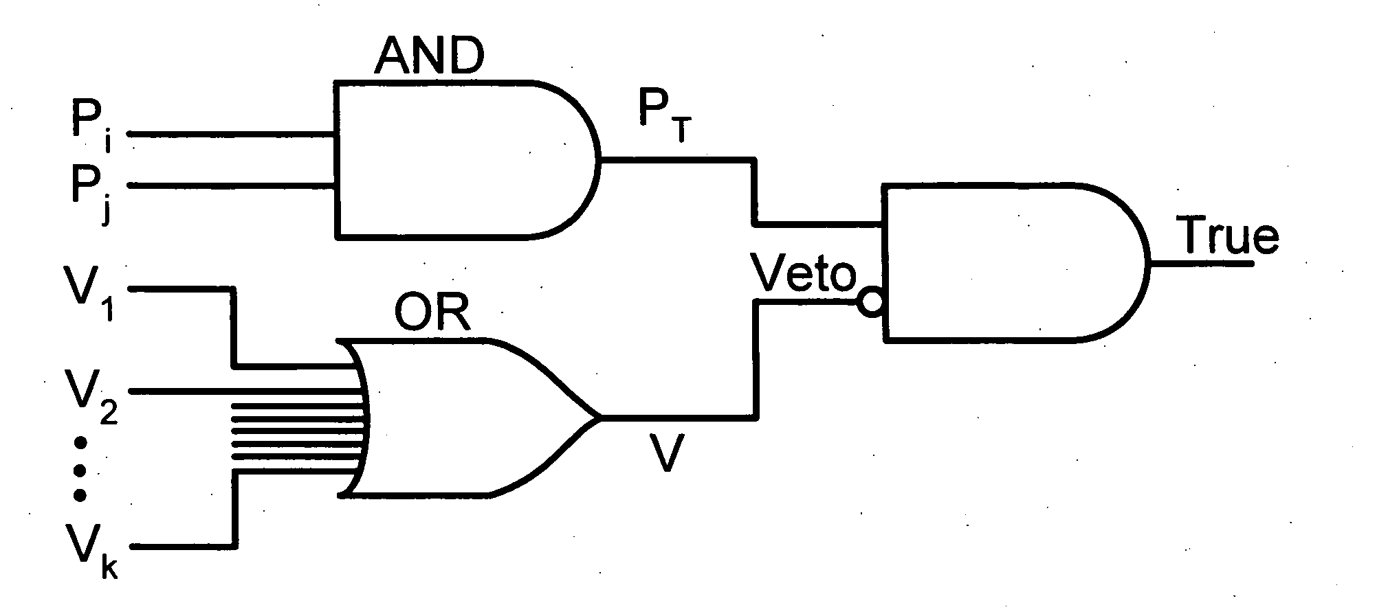
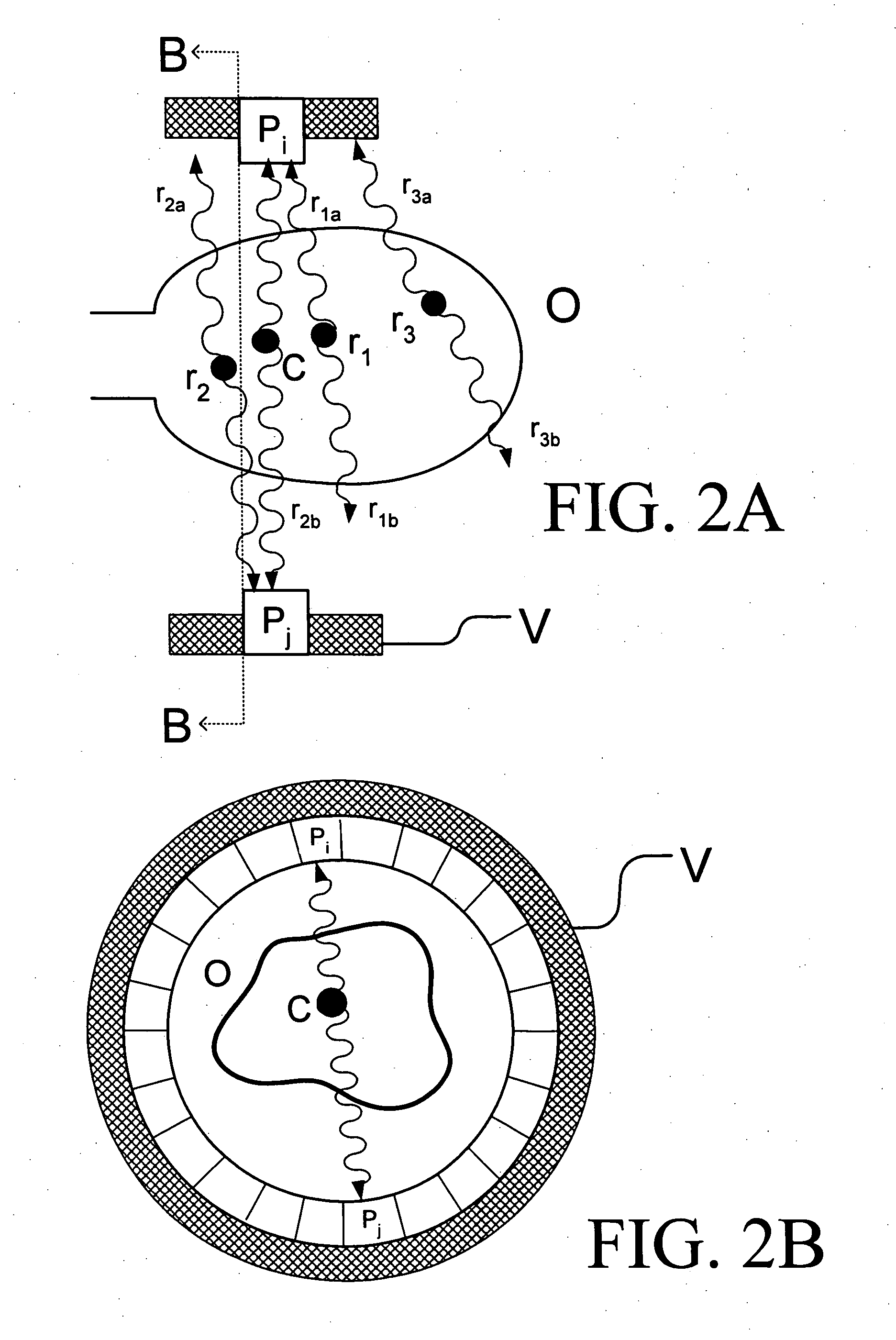
"The present invention is a new method for reducing or eliminating random coincidences in PET tomographs. It involves adding additional gamma ray detectors to a conventional PET spectrometer to detect photons that may be produced by random events. These detectors surround the primary detector ring and form a \"photon veto\" detector assembly. The veto detectors provide coverage of the object or patient so that most of the photons produced by random events are detected and registered. By excluding these photons, the quality of the detection data is improved and the precision and accuracy of the resulting image is increased. The positioning and coverage of the veto detectors are selected to balance the advantages and disadvantages of detecting extra photons and \"false vetoes,\" resulting in a more accurate image. The veto detector assembly may include various types of photon detectors that have the necessary timing resolution to veto random events. An electronic logic system is used to improve the ability of the imaging system to distinguish between \"true\" event photons and random event photons."

Problems solved by technology

The difficulty with all such detectors is that a large number of such detectors are necessary for accurate scanning, and the positions of interactions of gamma rays with the detectors must be determined with sufficient accuracy so that with the accumulation of, typically, millions of such determinations, sufficient data is obtained for producing an accurate image of the scanned object(s).
Because each of the detectors must be capable of generating position data for a gamma ray interaction, acquisition of such position data and the compilation thereof, e.g. by a computer, may require very substantial and expensive apparatus.
However, as can be appreciated, the monitoring instrumentation, including the photodetectors, logic circuits and related controller and signal devices (referred to collectively as a read-out channel) can result in very complex monitoring instrumentation, especially when a large number of detectors are required to obtain the desired accuracy in the intended scan.
In addition, a conventional detector for such gamma ray scanning devices is an inorganic scintillating crystalline material, e.g. cerium doped lutetium oxyorthosilicate (LSO) and bismuth germinate (BGO), which is, in and of itself, expensive.
This resolution and lack of uniformity results in a basic level of inaccuracy that precludes precise identification of exactly where in the detector, i.e. at which XY coordinates, that gamma ray interaction occurred.
In addition, the depth of the interaction, i.e. the Z coordinate, is generally not determined, or is determined with reduced accuracy in comparison to the X and Y coordinates, resulting in a so-called parallax error and further reducing the accuracy of the resulting image.
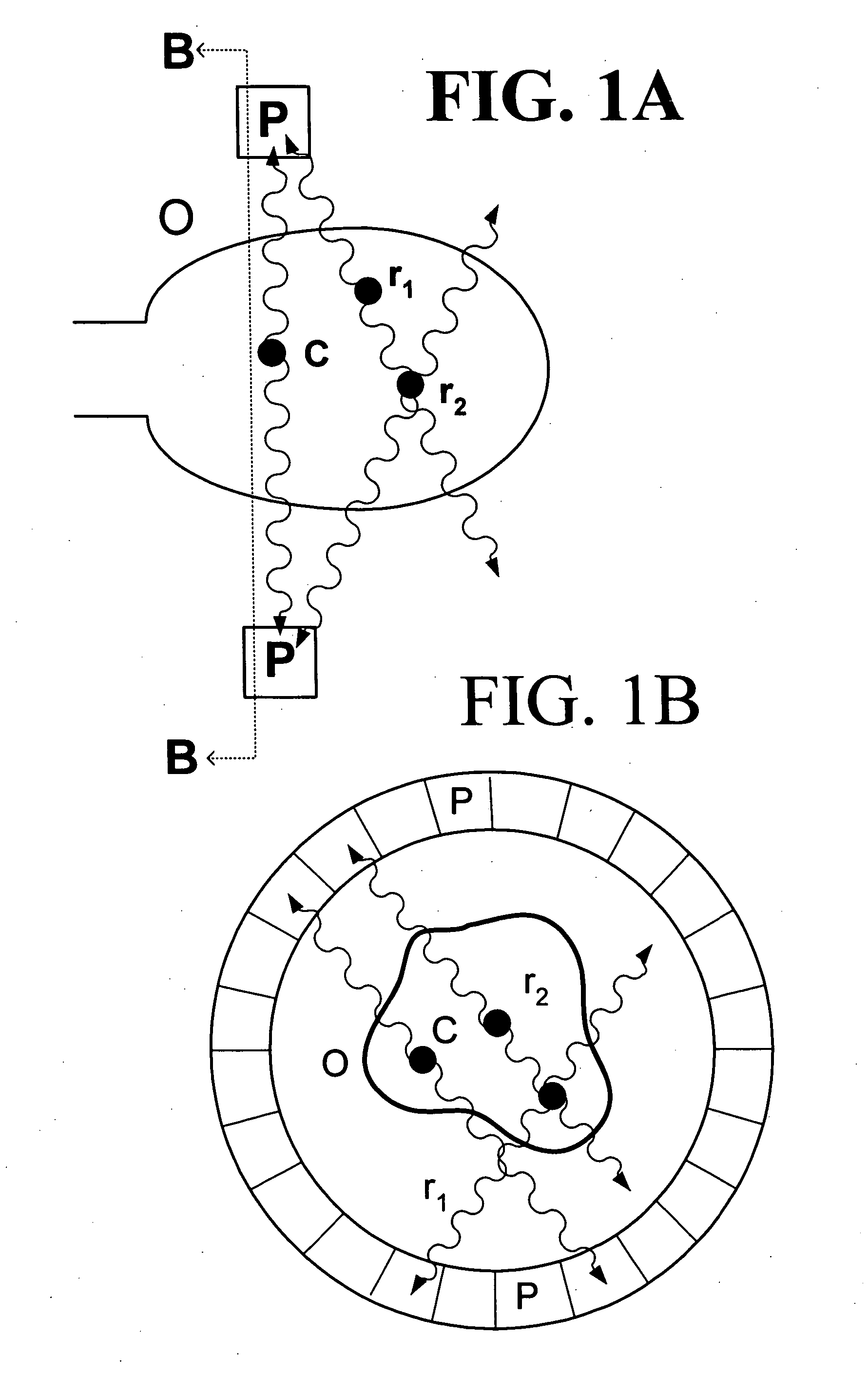
Images are generally limited in resolution by several factors including range of positrons, detector spatial and energy resolutions, scattering of photons in the object / patient under investigation before the photons reach the detectors, and scattering in the detectors.
In addition, random or accidental coincidences which occur when two or more photons from separate annihilation events are detected within the resolving time window of the apparatus limit the statistical precision of image reconstruction.

Method used


Image

  • Method and apparatus for vetoing random coincidences in positron emission tomographs
  • Method and apparatus for vetoing random coincidences in positron emission tomographs
  • Method and apparatus for vetoing random coincidences in positron emission tomographs

Examples


Embodiment Construction

[0027] The present invention is directed to an apparatus and method for eliminating or severely reducing random coincidences in PET tomographs, thereby improving the accuracy and resolution of the tomographs. The system consists of gamma ray detectors which are arranged to detect photons not registered in the tomograph along with an electronic logic system that vetoes or eliminates from further consideration those events in which additional signals are detected. In this manner, events with random coincidences will not substantially reduce the statistical significance of the image data consisting of true coincidences. Exemplary gamma ray detectors and their operation are detailed in the inventor's U.S. Pat. No. 6,100,532, and in published U.S. patent applicaltion No. 2004 / 0007670, the disclosures of both are hereby incorporated in their entirety by reference.

[0028] In conventional PET tomographs, signals from selected sets of detector element pairs are accepted if they occur within ...


PUM


Abstract

An improved gamma ray detector and method for discriminating between “true” pairs of gamma rays produced by a single positron annihilation event and those randomly occurring “pairs” of gamma rays that may fall within the conventional acceptance criteria for “true” pairs. The gamma ray detector incorporates an additional array of “veto” detectors arranged adjacent or around a primary detector array. The array of “veto” detectors is configured to detect gamma rays that escape detection in the primary detector array. The detection data from both the primary detector array and the veto detector array are used as inputs into a discrimination circuit for “vetoing” those pairs of gamma rays detected by the primary detector array that are likely to be the result of two or more unrelated positron annihilation events. By increasing the proportion of “true” events used in image reconstruction, the apparatus and method may improve the quality of the resulting image, reduce the image processing time and / or reduce the need for subsequent data collection and / or manipulation.

Description

PRIORITY STATEMENT [0001] This application claims priority under 35 U.S.C. § 119(e) to U.S. Provisional Patent Application No. 60 / 554,347, which was filed on Mar. 19, 2004, the contents of which is incorporated herein, in its entirety and for all purposes, by reference.BACKGROUND OF THE INVENTION [0002] Gamma ray detectors are used in a wide variety of apparatus, such as in positron emission tomograph (PET), single photon emission-computed tomograph (SPECT), explosive detectors, and the like. All of such apparatus depend upon, in part, detectors which can determine the position of interactions of gamma rays with the detectors, such that with a plurality of such position measurements, a scan of an object of interest can be made. These techniques are well known to those of skill in the art and will not, therefore, be further detailed herein. [0003] The difficulty with all such detectors is that a large number of such detectors are necessary for accurate scanning, and the positions of ...

Claims


Application Information

Patent Timeline
Patent Type & Authority Applications(United States)
IPC IPC(8): G01T1/164G01T1/172
CPCG01T1/172
Inventor BRYMAN, DOUGLAS
Owner ADVANCED APPLIED PHYSICS SOLUTIONS
Learn More