

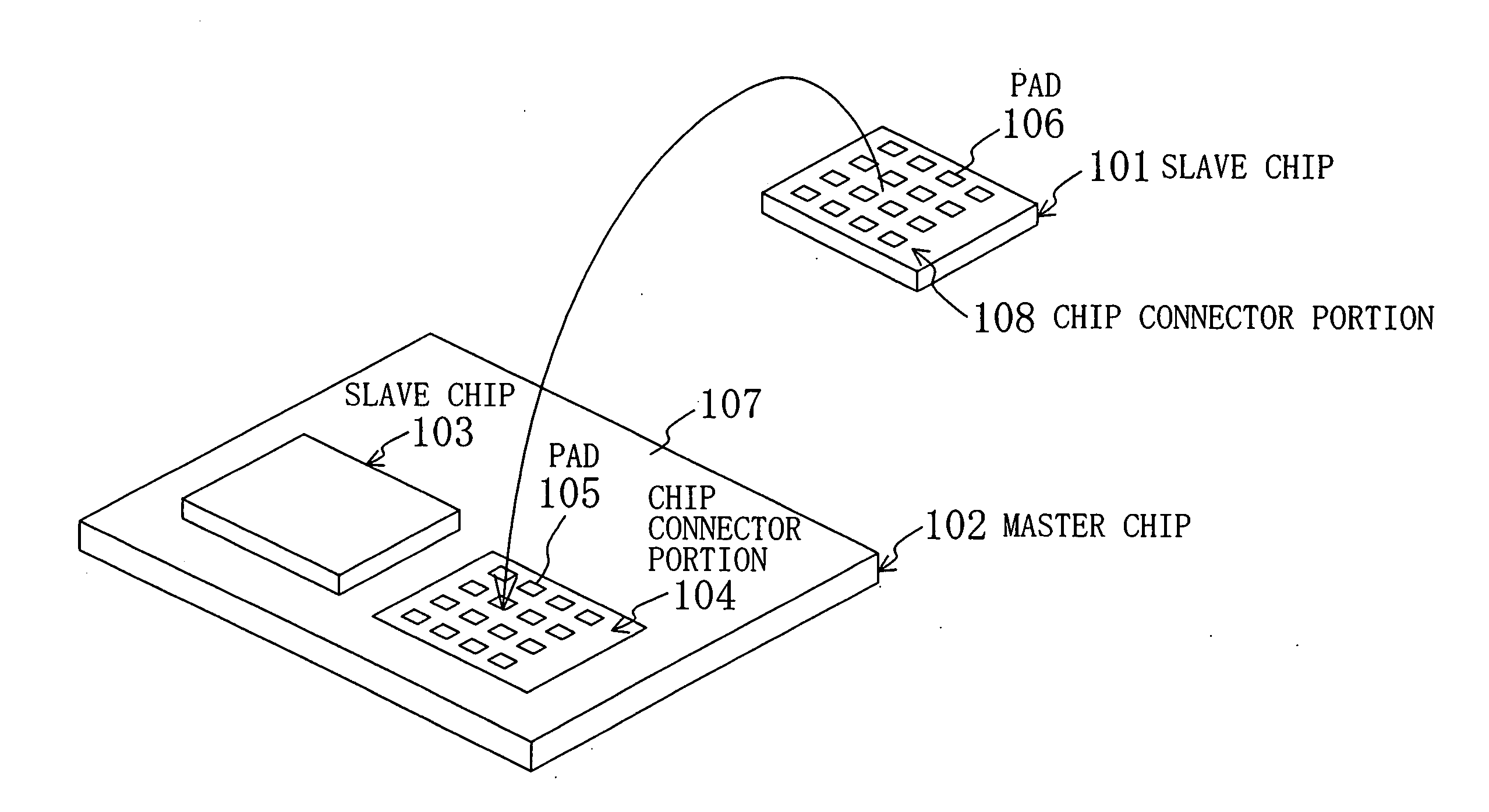
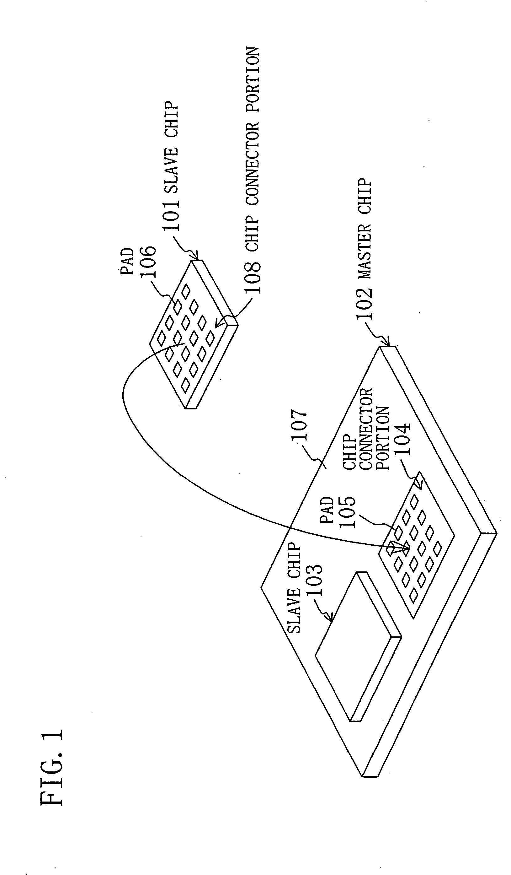
Semiconductor memory device and multi-chip module comprising the semiconductor memory device
a memory device and semiconductor technology, applied in the direction of semiconductor/solid-state device details, instruments, transistors, etc., can solve the problems of increasing manufacturing steps and accordingly the cost, inefficient power consumption in the conventional configuration in which all the memory cells are refreshed, and long time required to write data into all the memory cells, etc., to achieve the effect of reducing the test time for the memory cell array and burn-in testing time, preventing the operation of a refresh operation, and reducing the power consumption
- Summary
- Abstract
- Description
- Claims
- Application Information
AI Technical Summary
Benefits of technology
Problems solved by technology
Method used
Image

Examples
first modified example
of Row Decoder
[0063]FIG. 6 shows a first modified example of the row decoder 402, which is disposed on the memory cell array block 202 composed of, for example, a DRAM.
[0064] In the figure, reference numeral 600 denotes a block controlling pad (activation control terminal), which is one of the plurality of interchip connection pads 106 formed in the chip connector portion 400 and is a terminal for collectively controlling activation and inactivation of all the memory cells in each cell array portion 401 of the memory cell array block 202 during a refresh operation in which data are rewritten into the memory cells. Reference numeral 601 denotes a memory cell array block-activating signal, numeral 602 denotes a row address, numeral 603 denotes a first AND element, numeral 604 denotes a second group of AND elements, numeral 605 denotes a word driver, numeral 606 denotes a word line, numeral 607 denotes a memory cell, numeral 608 denotes a bit line, numeral 609 denotes a sense amplifie...
second modified example
of Row Decoder
[0072]FIG. 8 shows a second modified example of the row decoder 402 disposed on the memory cell array block 202.
[0073] In the figure, reference numeral 700 denotes a block controlling pad (all-the-word-lines-activating terminal), which is a terminal for activating all the word lines provided in the memory cell array block 202 in which the block controlling pad itself is provided, among a plurality of interchip connection pads 106 formed in the chip connector portion 400. Reference numeral 701 denotes a fourth group of AND elements, numeral 702 denotes a first group of OR elements, and numeral 703 denotes a fifth group of AND elements.
[0074] A predetermined row address 602 is input to the fourth group of AND elements 701. The outputs from the fourth group of AND elements 701 and the block controlling pad 700 are electrically connected to the inputs of the first group of the OR elements 702. The outputs from the first group of the OR elements 702 and the memory cell ar...
third modified example
of Row Decoder
[0082]FIG. 10 shows a third modified example of the row decoder 402 disposed on the memory cell array block 202.
[0083] In the figure, reference numeral 800 denotes, of the interchip connection pads 106, a block controlling pad (half-of-the-word-lines-activating terminal), which is a terminal for activating half of the word lines provided in the memory cell array block 202 in which the block controlling pad itself is provided according to the least significant bit (address signal) of the row address. Reference numeral 798 denotes an address decoder for even-numbered word lines, numeral 799 denotes an address decoder for odd-numbered word lines, numeral 801 denotes a sixth group of AND elements, numeral 802 denotes a second group of OR elements, numeral 803 denotes a sixth group of AND elements, numeral 804 denotes a seventh group of AND elements, numeral 805 denotes the least significant bit of the row address 602, and numeral 806 denotes a negative phase signal for th...
PUM
 Abstract
Description
Claims
Application Information