Power supply apparatus

a power supply and battery technology, applied in the field of power supply apparatuses, can solve the problems of one or more particular battery cells deteriorating, not all the battery cells deteriorating evenly, and the temperature of the battery cells becoming considerably high, so as to reduce the detection accuracy, reduce the cost, and improve the effect of accuracy

Inactive Publication Date: 2005-09-22
SANYO ELECTRIC CO LTD
View PDF3 Cites 43 Cited by
  • Summary
  • Abstract
  • Description
  • Claims
  • Application Information

AI Technical Summary

Benefits of technology

[0010] In view of the conventionally encountered inconveniences discussed above, it is an object of the present invention to provide a power supply apparatus that can detect the temperatures of individual battery cells with high accuracy and with a simple circuit design. It is another object of the present invention to provide a power supply apparatus that can control the lowering of the detection accuracy with which the temperatures of individual battery cells are detected even when an increased number of temperature sensors are used to detect the temperatures of the battery cells.

Problems solved by technology

In a power supply apparatus incorporating such a vehicle-driving battery, when the battery is made to discharge a large current to make a motor sharply accelerate an automobile, or when the battery is charged nearly to the fully-charged state with a large current while an automobile is running down with regenerative braking applied, or when the outside air temperature and thus the ambient temperature is abnormally high, or under other conditions, the temperatures of the battery cells become considerably high.
However, not all the battery cells deteriorate evenly; that is, only one or more particular battery cells may deteriorate.
Variations inevitable in the manufacturing process, differences in external / ambient factors such as the use temperature, etc. cause the individual battery cells to deteriorate unevenly.
If any battery cell deteriorates and the full capacity to which it can be charged becomes substantially smaller, charging and discharging that battery cell in the same way as the other battery cells cause it to be overcharged or overdischarged.
This makes the cell temperature higher, further promoting the deterioration.
Both types of secondary cell exhibit poorer characteristics at higher temperatures, and, at still higher temperatures, exhibit thermal runaway and quickly deteriorate.
However, in a case where a large number of PTC sensors are used, it is impossible to accurately detect the temperatures of the individual battery cells.
This is because it is difficult to give all the PTC sensors equal characteristics.
For example, with a circuit for detecting the temperatures of individual battery cells by the use of a large number of PTC sensors whose set temperature, i.e., the temperature over which their electrical resistance abruptly increases, includes an error of up to 10%, it is impossible to accurately detect, for all the battery cells, whether or not the temperatures of the individual battery cells are higher than the set temperature.
Moreover, in a case where, as disclosed in Patent Publication 1 mentioned above, a large number of PTC sensors are connected in series and their total electrical resistance is detected, the larger the number of PTC sensors serially connected, the more difficult it is to accurately detect the temperatures of the battery cells.

Method used


Image

  • Power supply apparatus
  • Power supply apparatus
  • Power supply apparatus

Examples


first embodiment

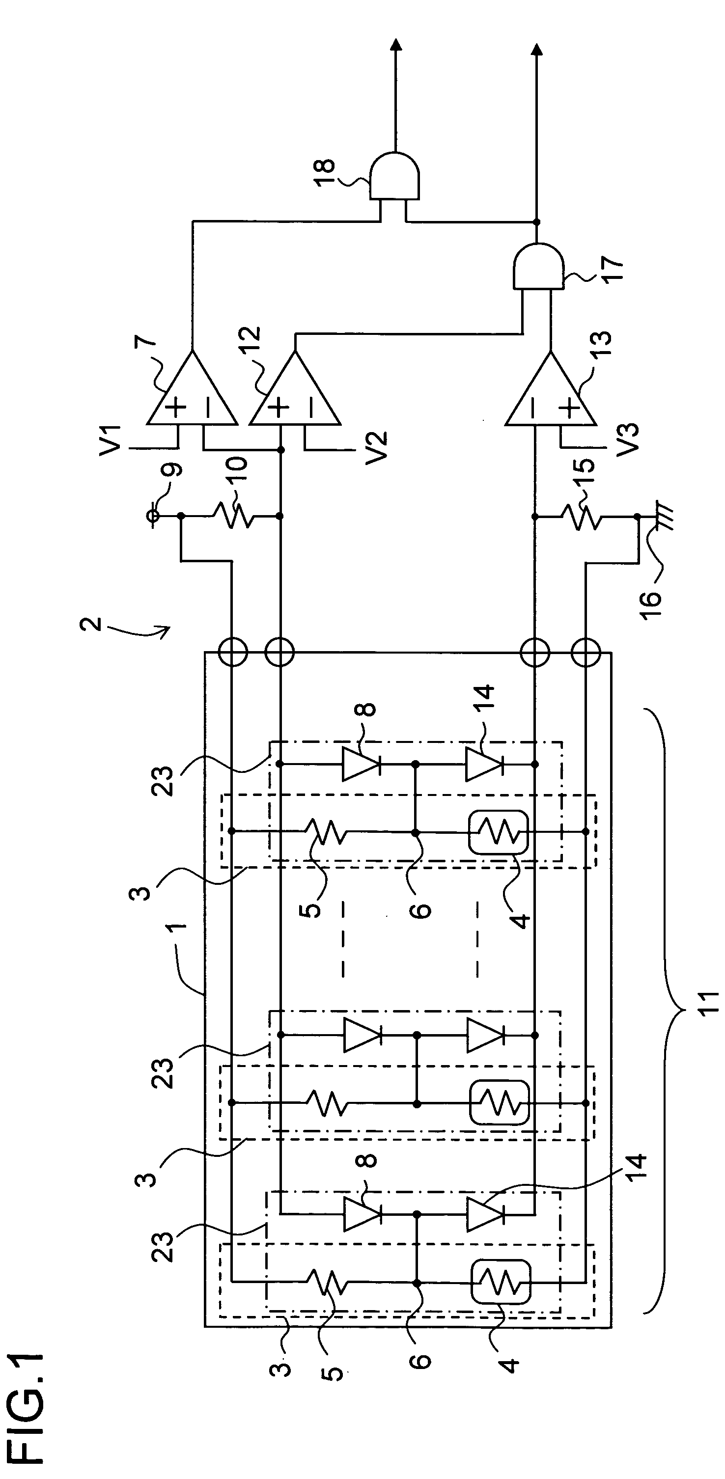
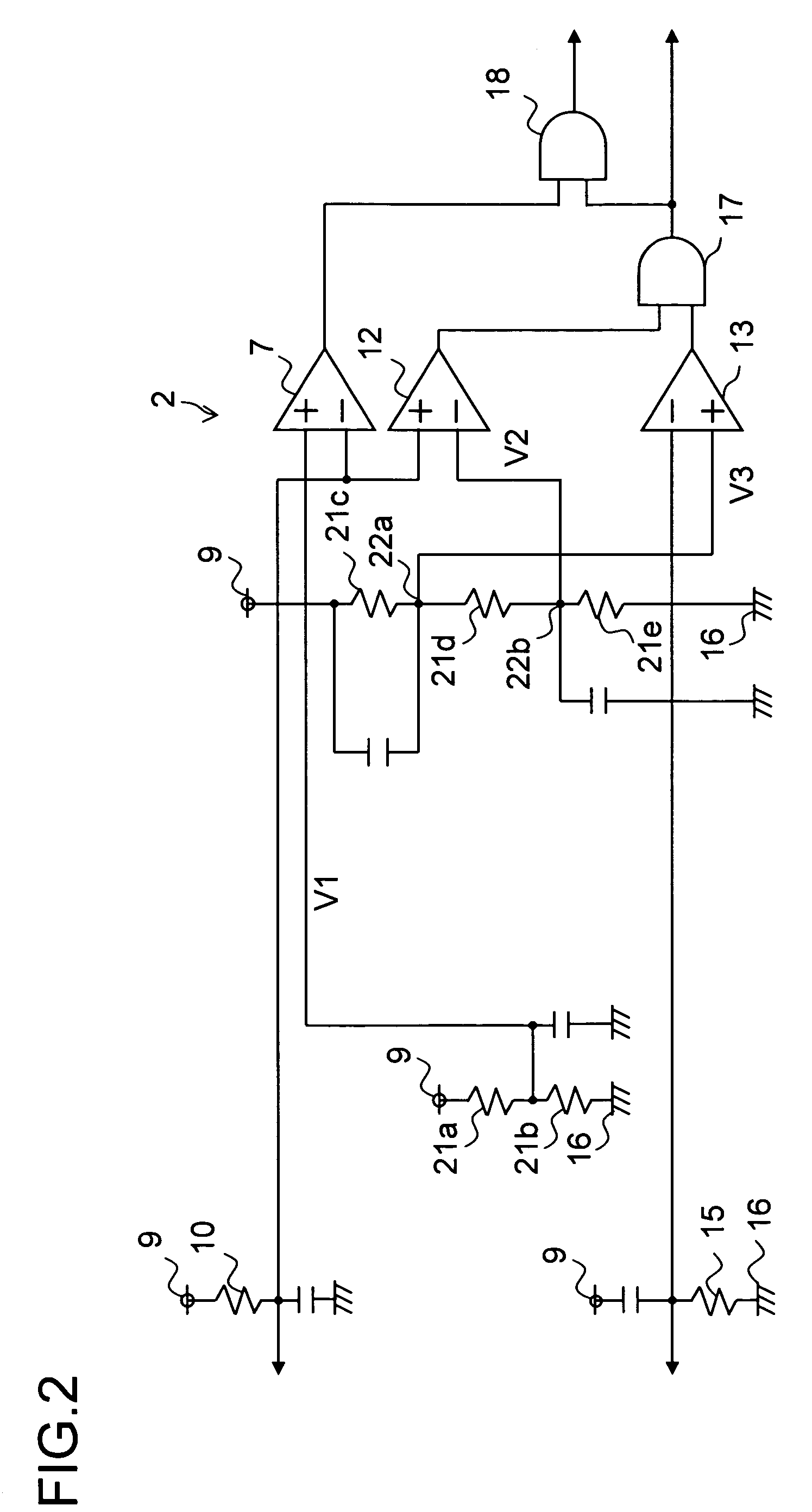
[0049] Hereinafter, the power supply apparatus of a first embodiment of the present invention will be described with reference to the drawings. It should be understood that the first embodiment described below and the second and third embodiments that will be described later are all intended merely to present examples of power supply apparatuses in which the technical idea of the present invention is embodied, and thus none of the power supply apparatuses specifically presented below is meant to limit the present invention in any way.

[0050] Power supply apparatuses embodying the invention (the power supply apparatus of the first, second, and third embodiments of the invention) are mounted on vehicles (not illustrated) such as hybrid cars, electric automobiles, and electric forklifts, or vehicles or the like (not illustrated) that run indoors to transport goods, so as to be used as power sources for driving the motors (not illustrated) that make those vehicles run. Power supply appa...

second embodiment

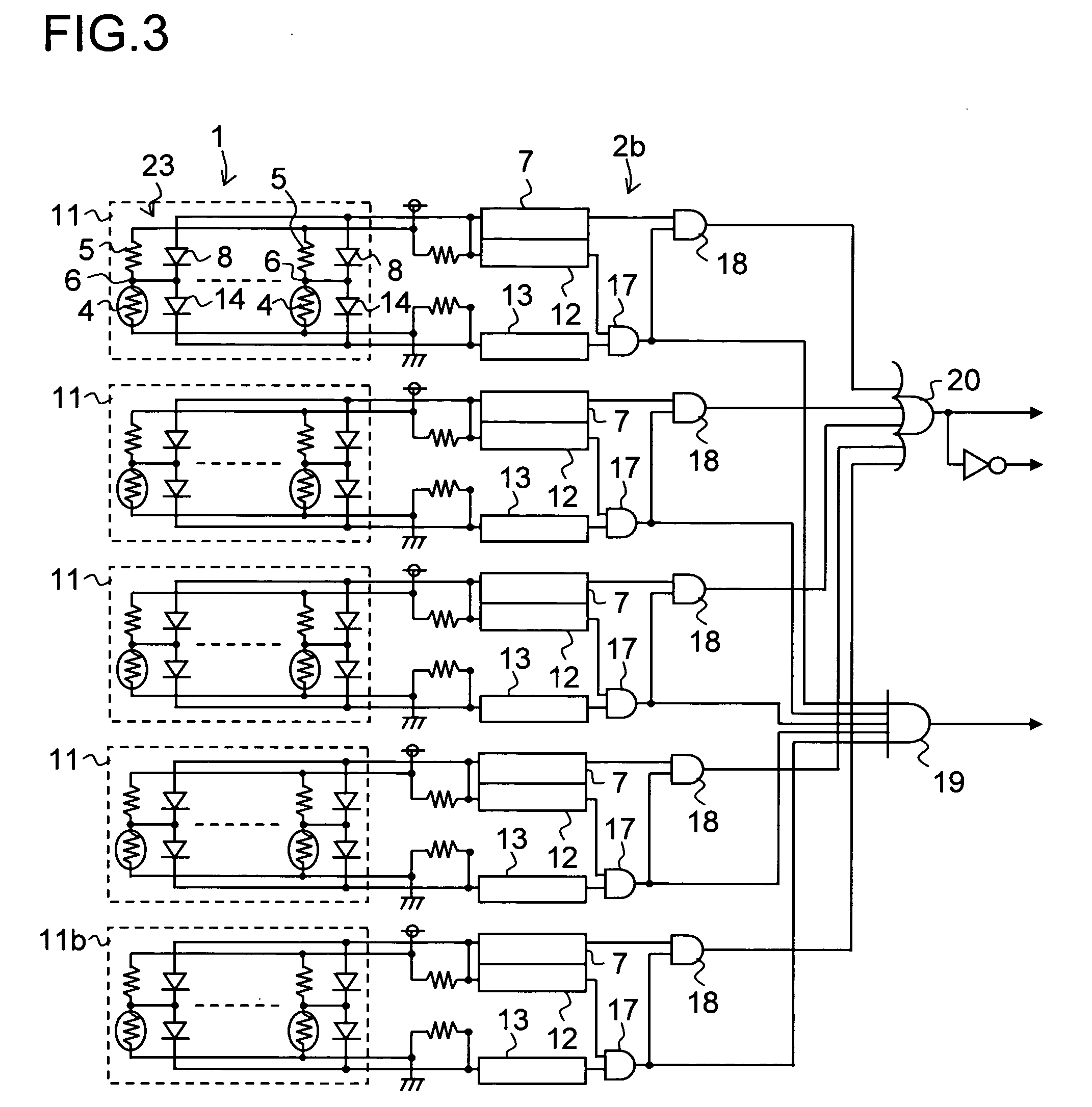
[0085] Next, the power supply apparatus of a second embodiment of the present invention will be described with reference to the drawings. FIG. 3 shows a circuit diagram of the power supply apparatus of the second embodiment. In FIG. 3, such portions as are found also in the FIG. 1 are identified with common symbols, and no explanations of their design and operation will be repeated.

[0086] The power supply apparatus shown in FIG. 3 includes: a battery 1; and a temperature detection circuit 2b for detecting the temperature of the battery 1. The temperature detection circuit 2b includes four temperature sensor circuits 11 and one temperature sensor circuit 11b. The battery 1 is composed of, for example, 130 battery cells 3 connected in series with one another, and the temperatures of these 130 battery cells 3 are detected by the four plus one temperature sensor circuits 11 and 11b. For example, the four temperature sensor circuits 11 each have 30 temperature detection units 23 so that...

third embodiment

[0092] Next, the power supply apparatus of a third embodiment of the present invention will be described with reference to the drawings. FIG. 5 shows a circuit diagram of the power supply apparatus of the third embodiment. In FIG. 5, such portions as are found also in the FIG. 1 are identified with common symbols, and no explanations of their design and operation will be repeated.

[0093] The power supply apparatus shown in FIG. 5 includes: a battery 1; and a temperature detection circuit 2a for detecting the temperature of the battery 1. The temperature detection circuit 2a includes: the same number of temperature detection units 23a as there are battery cells 3 (i.e., n temperature detection units 23a), with the temperature detection units 23a used to detect the temperatures of the battery cells 3 individually; a power supply (power supply circuit) 9; a first comparator 7a; a second comparator 12a; a third comparator 13a; a pull-down resistor 10a; and a pull-up resistor 15a. The n ...


PUM


Abstract

A power supply apparatus has a battery and a temperature detection circuit. The battery has n battery cells, and the temperature detection circuit has m temperature detection units. Each temperature detection units has a temperature sensor that is thermally coupled to one or more of the battery cells and whose electrical resistance decreases as the temperature of the battery cell or battery cells to which it is thermally coupled increases, a serial resistor that is connected in series with the temperature sensor, and a first diode whose cathode is connected to the node between the temperature sensor and the serial resistor. The serial circuit formed by the temperature sensor and the serial resistor receives a predetermined voltage such that, as the electrical resistance of the temperature sensor decreases, the voltage at the node decreases. The first diodes have anodes thereof connected together.

Description

[0001] This application is based on Japanese Patent Applications Nos. 2004-077318 and 2005-49235 filed on Mar. 18, 2004 and Feb. 24, 2005, respectively, the contents of which are hereby incorporated by reference. BACKGROUND OF THE INVENTION [0002] 1. Field of the Invention [0003] The present invention relates to a power supply apparatus for use, for example, in a vehicle to drive a motor for making the vehicle run, or in an electric appliance to drive a load. More particularly, the present invention relates to a power supply apparatus incorporating a temperature detection circuit for detecting the temperature of a battery. [0004] 2. Description of Related Art [0005] A vehicle-driving battery for supplying electric power to a motor for driving a vehicle yields a high output voltage thanks to a large number of battery cells, secondary cells, connected in series. This permits a motor to yield an output high enough to make an automobile run. In a power supply apparatus incorporating suc...

Claims


Application Information

Patent Timeline
Patent Type & Authority Applications(United States)
IPC IPC(8): G01K1/02G01K1/14G01K3/00G01K3/14G01K7/24G01R31/36H01M10/48H02H5/04H02J7/04
CPCB60L3/0046B60L2240/545B60L2240/547B60L2240/549G01K1/026H01M10/486G01K3/14G01K7/24G01R31/3675G01R31/3682H01M10/482G01K3/00G01R31/374G01R31/3646B60L58/18B60L58/24Y02T10/70Y02E60/10
Inventor SEO, KAZUHIROFURUKAWA, KIMIHIKOARAI, ISAO
Owner SANYO ELECTRIC CO LTD
Why Eureka
Try Eureka