Electrical devices and anti-scarring agents

a technology of electric devices and anti-scarring agents, which is applied in the field of pharmaceutical compositions, methods and devices, can solve the problems of shortening the battery life of implants, reducing the performance of implants, and reducing the clinical effectiveness of implants, so as to reduce the foreign body response to implantation, reduce the growth of reactive tissue, and enhance performance

Inactive Publication Date: 2005-09-22
ANGIOTECH INT AG (CH)
View PDF22 Cites 120 Cited by
  • Summary
  • Abstract
  • Description
  • Claims
  • Application Information

AI Technical Summary

Benefits of technology

[0017] The pharmaceutical agents and compositions are utilized to create novel drug-coated implants and medical devices that reduce the foreign body response to implantation and limit the growth of reactive tissue on the surface of, or around in the tissue surroundin...

Problems solved by technology

This can shorten the battery life of an implant (making more frequent removal and re-implantation necessary), prevent electrical conduction altogether (rendering the implant clinically ineffective) and/or cause damage to the target tissue.
In medical...

Method used


Image

  • Electrical devices and anti-scarring agents
  • Electrical devices and anti-scarring agents
  • Electrical devices and anti-scarring agents

Examples


example 1

Parylene Coating

[1028] A metallic portion of an electrical device (e.g., a neurostimulator or an electrical lead) is washed by dipping it into HPLC grade isopropanol. A parylene primer layer (about 1 to 10 um) is deposited onto the cleaned electrical device using a parylene coater (e.g., PDS 2010 LABCOATER 2 from Cookson Electronics) and di-p-xylylene (PARYLENE N) or dichloro-di-p-xylylene (PARYLENE D) (both available from Specialty Coating Systems, Indianapolis, Ind.) as the coating feed material.

example 2

Paclitaxel Coating—Partial Coating

[1029] Paclitaxel solutions are prepared by dissolving paclitaxel (5 mg, 10 mg, 50 mg, 100 mg, 200 mg and 500 mg) in 5 ml HPLC grade THF. A coated portion of a parylene-coated device (as prepared in, e.g., Example 1) is dipped into a paclitaxel / THF solution. After a selected incubation time, the device is removed from the solution and dried in a forced air oven (50° C.). The device then is further dried in a vacuum oven overnight. The amount of paclitaxel used in each solution and the incubation time is varied such that the amount of paclitaxel coated onto the device is in the range of 0.06 μg / mm2 to 10 μg / mm2 (μg paclitaxel / mm2 of the device which is coated with paclitaxel after being placed in the THF / paclitaxel solution). The time during which the device is maintained in the paclitaxel / THF solution may be varied, where longer soak times generally provide for more paclitaxel to be adsorbed onto the device. In additional examples, one of the follo...

example 3

Paclitaxel Coating—Complete Coating

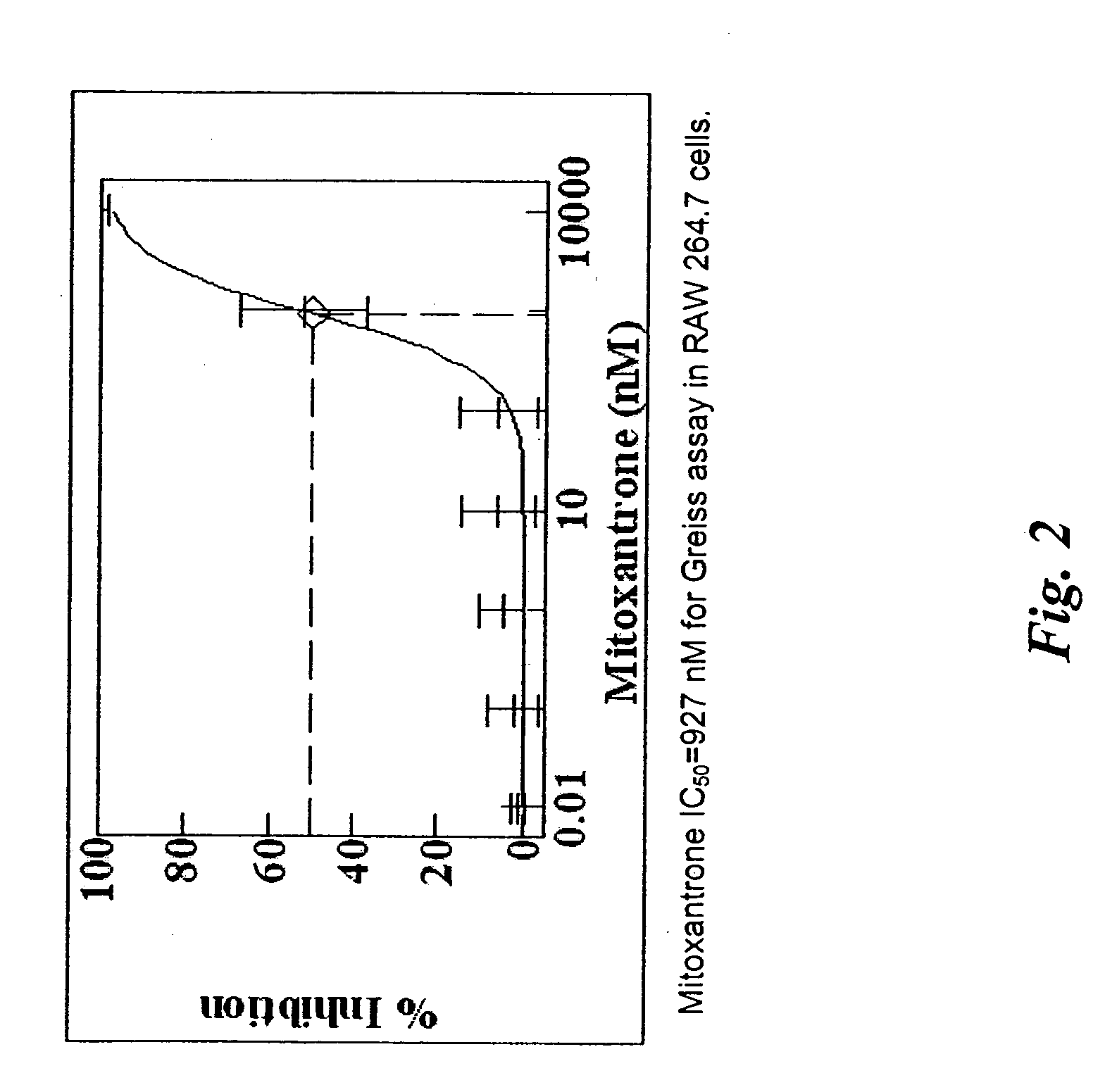
[1030] Paclitaxel solutions are prepared by dissolving paclitaxel (5 mg, 10 mg, 50 mg, 100 mg, 200 mg and 500 mg) in 5 ml HPLC grade THF. An entire parylene coated device (coated as in, e.g., Example 1) is then dipped into the paclitaxel / THF solution. After a selected incubation time, the device is removed and dried in a forced air oven (50° C.). The device is then further dried in a vacuum oven overnight. The amount of paclitaxel used in each solution and the incubation time is varied such that the amount of paclitaxel coated onto the device is in the range of 0.06 μg / mm2 to 10 μg / mm2. In additional examples, one of the following exemplary compounds may be used in lieu of paclitaxel: mitoxantrone, doxorubicin, epithilone B, etoposide, TAXOTERE, tubercidin, halifuginone, vinblastine, geldanamycin, simvastatin, sirolimus, everolimus, pimecrolimus, mycophenolic acid, 1-alpha-25 dihydroxy vitamin D3, Bay 11-7082, SB202190, mithramycin and sulconizole...


PUM

PropertyMeasurementUnit
Acidityaaaaaaaaaa
Deposition rateaaaaaaaaaa

Abstract

Electrical devices (e.g., cardiac rhythm management and neurostimulation devices) for contact with tissue are used in combination with an anti-scarring agent (e.g., a cell cycle inhibitor) in order to inhibit scarring that may otherwise occur when the devices are implanted within an animal.

Description

CROSS-REFERENCE TO RELATED APPLICATIONS [0001] This application is a Continuation-in-Part of U.S. application Ser. Nos. 10 / 986,231, filed Nov. 10, 2004; and 10 / 986,230, filed Nov. 10, 2004. This application also claims the benefit under 35 U.S.C. 119(e) of U.S. Provisional application Ser. Nos. 60 / 586,861, filed Jul. 9, 2004; 60 / 578,471, filed Jun. 9, 2004; 60 / 526,541, filed Dec. 3, 2003; 60 / 525,226, filed Nov. 24, 2003; 60 / 523,908, filed Nov. 20, 2003; and 60 / 524,023, filed Nov. 20, 2003, which applications are incorporated herein by reference in their entireties.BACKGROUND OF THE INVENTION [0002] 1. Field of the Invention [0003] The present invention relates generally to pharmaceutical compositions, methods and devices, and more specifically, to compositions and methods for preparing and using medical implants to make them resistant to overgrowth by inflammatory, fibrous and glial scar tissue. [0004] 2. Description of the Related Art [0005] Medical devices having electrical compon...

Claims


Application Information

Patent Timeline
IPC IPC(8): A61L31/10A61L31/16A61N1/00A61N1/36A61N1/372
CPCA61L31/10A61L31/16A61L2300/404A61L2300/416A61L2300/432A61N1/3605A61N1/372C08L89/00C08L31/04C08L75/04
Inventor HUNTER, WILLIAM L.GRAVETT, DAVID M.TOLEIKIS, PHILIP M.MAITI, ARPITA
Owner ANGIOTECH INT AG (CH)
Why Eureka
Try Eureka