Everting stent and stent delivery system

a technology of stent and stent, which is applied in the field of stents, can solve the problems of limiting efficacy, myocardial infarction, even death, and limiting efficacy, so as to prevent large pieces from breaking off, stabilize the thrombus, and stabilize the thrombus

Inactive Publication Date: 2005-09-22
COVIDIEN LP
View PDF2 Cites 47 Cited by
  • Summary
  • Abstract
  • Description
  • Claims
  • Application Information

AI Technical Summary

Benefits of technology

[0015] Some methods according to the present invention can utilize a guide wire to facilitate advancement of a guide catheter or microcatheter to a location near the vessel region to be stented. The guide wire can be retracted, and the carried everted stent advanced by the release member and guide tube together through the guide catheter or microcatheter to the target region. In one method, the everted stent carried by the delivery tube and release member are advanced distally from the guide catheter to cross the target region, for example, a blood vessel stenosis. In another method, the microcatheter together with the everted stent carried by the delivery tube and release member are advanced through the stenosis or other blockage, followed by proximally retracting the microcatheter, leaving the everted stent to expand against the target region vessel or blockage walls. Once the everted stent is in location, the release member can be activated by advancing or retracting the member to free the everted stent.
[0017] In another use of the present invention, an everted porous stent carried by a delivery tube can be distally advanced through a thrombosed blood vessel region. A wire mesh or braided stent may be used. The everted stent can be released from the delivery tube to expand against the thrombus. The delivered stent can thus act to stabilize the thrombus. After stenting, the thrombus can be treated by infusing thrombolytic agents near the thrombus, through the walls of the porous stent. The stent can thus act to stabilize the thrombus, preventing large pieces from breaking off and being carried downstream during the thrombolysis.
[0018] Some embodiments of the present invention have distally tapered delivery tubes having very small distal end profiles. In these embodiments, the release member distal element may be very small in profile as well. The limit of the distal profile in such devices may approach the lower size limit in gathering, everting, and compressing the distal region of the stent to be delivered. In these and other embodiments, the leading edge of the stent delivery device can be very benign and atraumatic due to the everted stent forming the distal-most leading edge of the device. Many embodiments of the device thus eliminate the absolute need for a delivery sheath or tube disposed about the stent, thereby eliminating one set of tube profiles from the device, making the distal region more flexible, smaller in profile, and able to reach even more distal and smaller diameter vessels which will benefit from treatment.

Problems solved by technology

The vessel regions thus partially occluded can cause angina and, when totally occluded, myocardial infarction, and even death.
This re-narrowing or restenosis, limits the efficacy of the angioplasty procedures, may require further angioplasty, or can lead to myocardial infarction and even death.
The loss of oxygen can rapidly cause brain death in the affected brain regions if the blockage is not soon treated.
The required timing and difficult vessel characteristics make reaching and treating the thrombus to prevent brain cell death a most difficult task.
The narrow cerebral vessels make placing stents within the brain very difficult using current stents and stent delivery systems.
(1⅓ mm.) in outer diameter, currently being generally unsuitable for delivery of cerebral stents.
The composite structure is thus not as flexible as either the stent or sheath alone would be in traversing these passages.
In particular, this may leave smaller vessels unreachable and untreatable.
Sites requiring treatment disposed on the distal side of a tortuous curve may also be unreachable and untreatable.
In use, some currently available stents and delivery systems also have another limitation.
It may be nearly impossible to predict the final stent length before the stent is fully expanded in the vessel.
The difficulty in accurate stent placement can become an issue in stenting a vessel ostium.
If the stent is positioned too proximal, the stent extends into the trunk line, and can cause flow disturbance.

Method used


Image

  • Everting stent and stent delivery system
  • Everting stent and stent delivery system
  • Everting stent and stent delivery system

Examples


Embodiment Construction

[0026] The following detailed description should be read with reference to the drawings, in which like elements in different drawings are numbered identically. The drawings, which are not necessarily to scale, depict selected embodiments and are not intended to limit the scope of the invention. Several forms of invention have been shown and described, and other forms will now be apparent to those skilled in art. It will be understood that embodiments shown in drawings and described above are merely for illustrative purposes, and are not intended to limit scope of the invention as defined in the claims that follow.

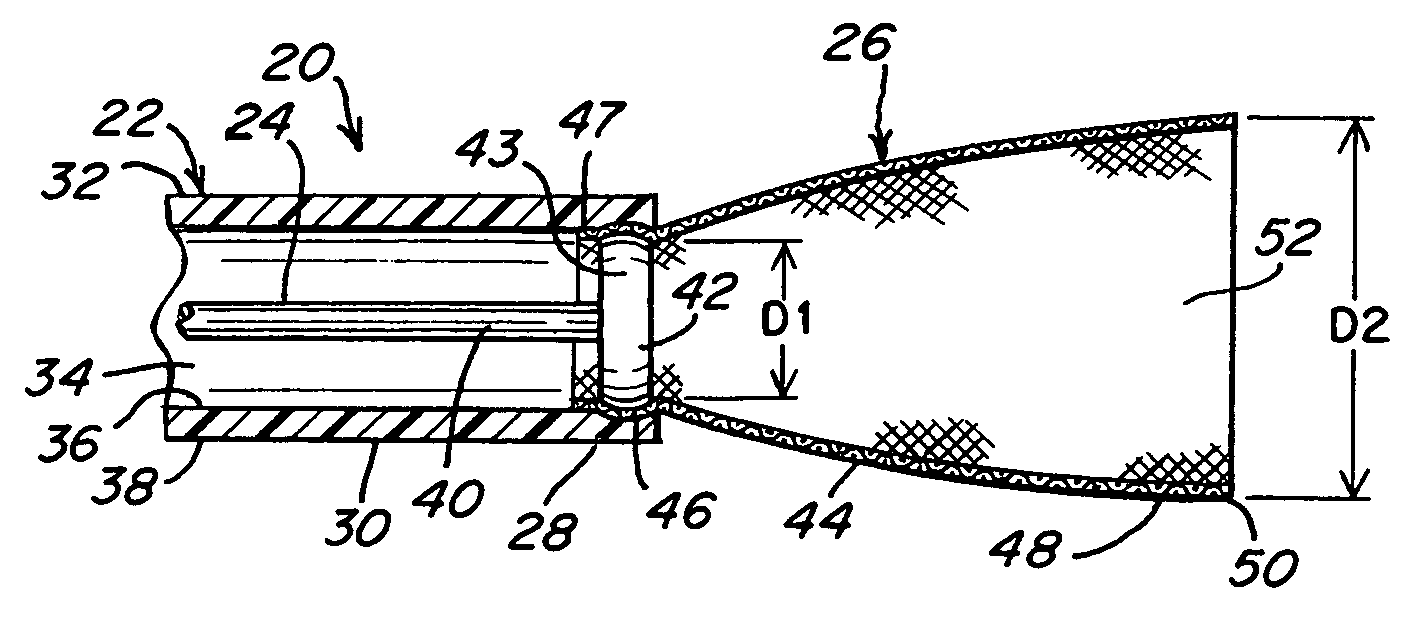
[0027]FIG. 1 illustrates a stent delivery assembly including a stent delivery device 20, a stent 26, a delivery shaft or tube 22, and an elongate release member 24. Release member 24 can be used to releasably secure or couple stent 26 to delivery shaft or tube 22. Stent26 is illustrated in a configuration prior to being everted and proximally disposed about delivery tube 2...


PUM


Abstract

Devices and methods for delivering stents to target vessel regions, including stent delivery through microcatheters to narrow cerebral arteries. One stent delivery device includes a stent having the distal region everted over the distal end of a delivery tube, having the everted stent distal end captured by a distal element of a elongate release member disposed through the delivery tube. The delivery tube can have a distal taper to a small profile distal end. The everted stent distal region can be captured between the release member distal element and the surrounding delivery tube distal region walls. The captured and everted stent can be distally advanced to a target site, followed by manipulating the release member to free the captured stent. Some devices utilize distal advancement of the release member while other devices use proximal retraction of the release member to free the captured stent distal end. Once released, the stent is free to self-expand or be expanded against the surrounding blockage and / or vessel walls. In some methods, a guide catheter or microcatheter is also included and disposed about the everted and captured stent to advance the stent, delivery tube, and release member to a location near the site to be stented. The devices and methods provide stent delivery not requiring an enclosing delivery sheath about the stent. The everted stent can thus have a very small distal profile enabling small diameter vessels to be crossed and treated.

Description

FIELD OF THE INVENTION [0001] The present invention relates generally to medical devices. More specifically, the present invention relates to stents. The stents may find particular use in intravascular procedures in general, and in cardiovascular procedures in particular, as well as other areas. BACKGROUND OF THE INVENTION [0002] Stents are well known to those skilled in the biomedical arts. In particular, stents are commonly used in cardiovascular applications. Stents have gained increasing acceptance, particularly when used in conjunction with minimally invasive procedures such as angioplasty. Blockages of the coronary arteries may result from various causes, including plaque build-up, and stenosed or thrombosed vessel regions. The vessel regions thus partially occluded can cause angina and, when totally occluded, myocardial infarction, and even death. Minimally invasive procedures such as balloon angioplasty have been used to dilate such blocked vessel regions, thereby at least p...

Claims


Application Information

Patent Timeline
Patent Type & Authority Applications(United States)
IPC IPC(8): A61F2/06
CPCA61F2/95A61F2/82
Inventor KUSLEIKA, RICHARD
Owner COVIDIEN LP
Why Eureka
Try Eureka