Pulse detonation engine system for driving turbine

a technology of pulse detonation engine and driving turbine, which is applied in the direction of engine starter, turbine/propulsion engine ignition, machines/engines, etc., can solve the problems of turbine temperature excessive rise, turbine damage, and possible bearing seizur

Active Publication Date: 2005-09-29
IHI CORP
View PDF21 Cites 31 Cited by
  • Summary
  • Abstract
  • Description
  • Claims
  • Application Information

AI Technical Summary

Benefits of technology

[0009] However, such a pulse detonation engine is applicable to not only the propulsion engines described above but also wider area of technical fields such as

Problems solved by technology

(see FIG. 1C), produced by the pulse detonation engine, causes an inlet temperature of a turbine to excessively rise.
Also, if a turbine directly receives impact energies of detonation waves (shock waves) released to the outside of the detonation tube, the turbine may be damaged.
Further, since bearings (for instance, thrust bearings) for supporting a rotor shaft of the turbine are liable to bear large loads oriented in an axial direction, when the turbine is driven by the pulse detonation engine, seizure of the bearings may occur because motive gases intermittently flow from the pulse detonation engine into the turbine.
Although one of approaches to solve this issue is designed in inc

Method used


Image

  • Pulse detonation engine system for driving turbine
  • Pulse detonation engine system for driving turbine
  • Pulse detonation engine system for driving turbine

Examples


first embodiment

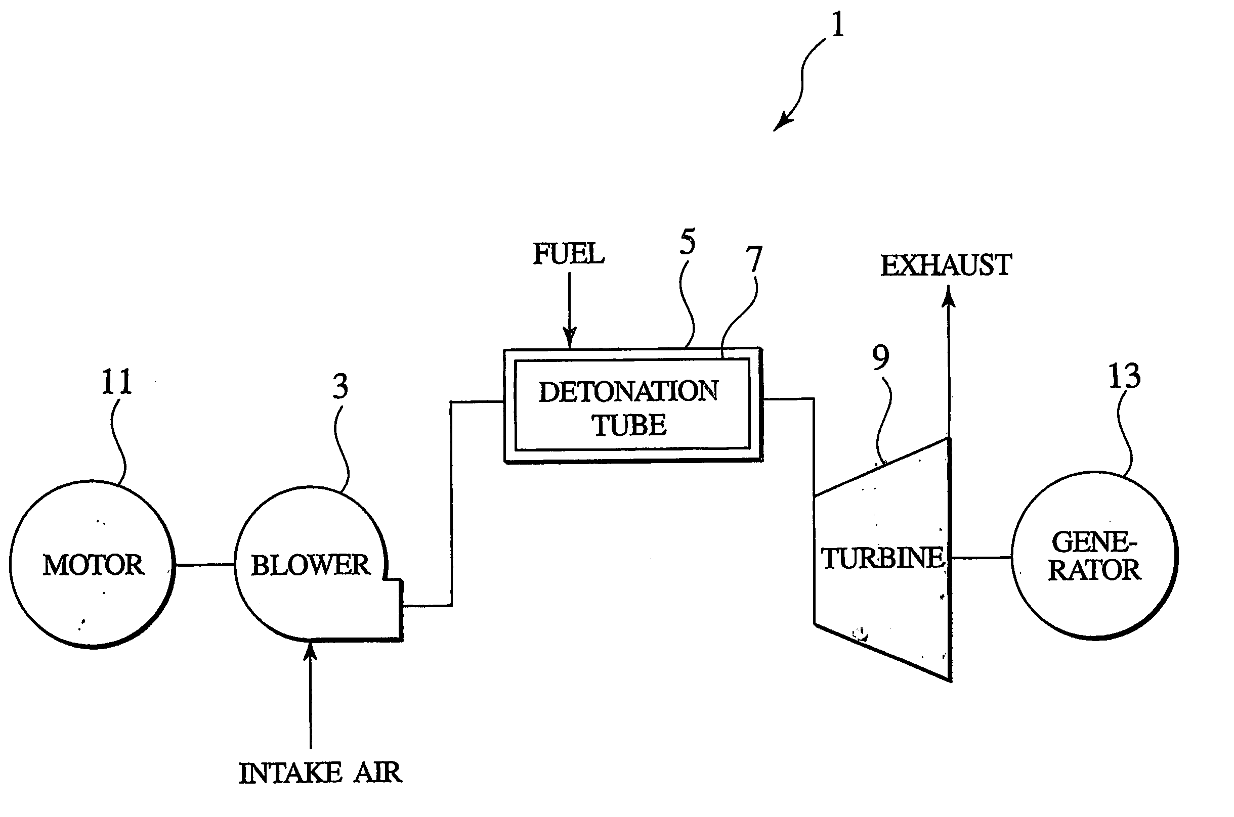
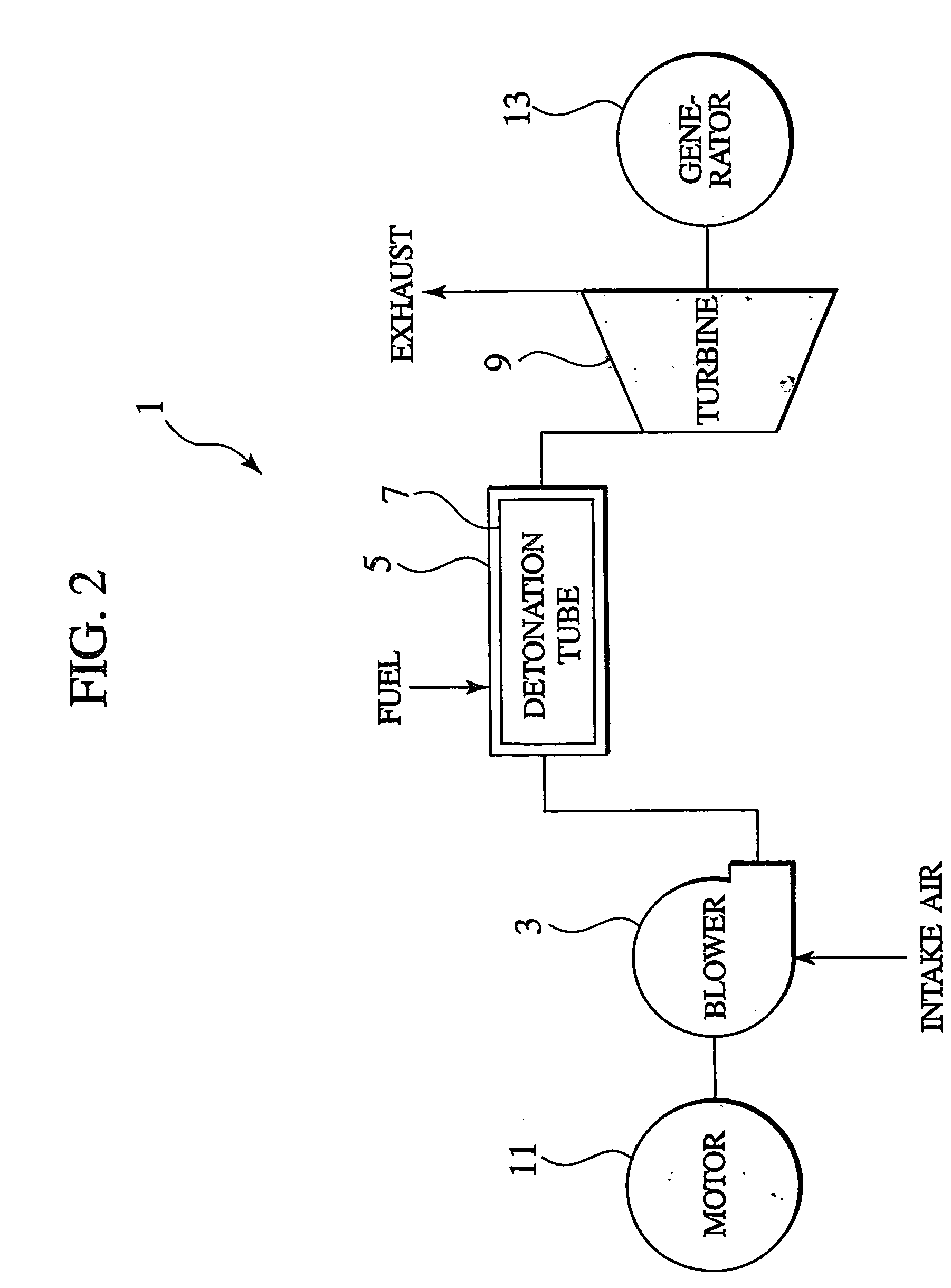
[0028]FIG. 2 shows a schematic structure of a pulse detonation engine system for driving a turbine 1 of the present invention. FIG. 3 shows a schematic structure of a detonation generator section 5 shown in FIG. 2.

[0029] The turbine drive pulse detonation engine system 1 of the present invention intermittently produces pulsed detonation waves with impact energies in combustion processes of heat cycles, and convert impact energies of detonation waves into motive power necessary for generating electric power.

[0030] The turbine drive pulse detonation engine system 1 includes a detonation generator section 5 that is comprised of a detonation tube 7 having a tubular hollow section formed in a given length to allow detonations to be produced therein, a gas supply section (for instance, an air valve) 17 for feeding a gas (for instance, oxidant such as air) into the tubular hollow section of the detonation tube 7, a fuel supply section (for instance, a fuel valve) 19 for feeding a fuel int...

fourth embodiment

[0041]FIG. 7 shows a concrete structure of a turbine drive pulse detonation engine driven electric power generation system 1C of the present invention.

[0042] The turbine drive pulse detonation engine driven electric power generation system 1C includes a detonator generator section 45 that is comprised of a detonation tube 47 having a tabular hollow section extending in a given length to allow detonation to be produced therein, a blower 43 for feeding a gas (for instance, oxidant such as air) into the tubular hollow section of the detonation tube 47 at given time intervals, a reformer (fuel supply section) 55 by which a fuel is fed into the tubular hollow section of detonation tube 47 at the given time intervals, and an igniter (not shown) that ignites a mixture combined with the reformed fuel and the air in the detonation tube 47. Also, air drawn from the blower 43 is fed into the detonation tube 47 through an air sump 49 and an air valve (gas supply section) 51. Moreover, the refor...

fifth embodiment

[0048]FIGS. 8 and 9 show a turbine drive pulse detonation engine system 1D, equipped with a reformer, of the present invention. FIG. 8 shows a schematic structure of the turbine drive pulse detonation engine system 1D. FIG. 9 shows a schematic structure of a detonation generator section 105 show in FIG. 8.

[0049] The turbine drive pulse detonation engine system 1D is comprised of a detonation generator section 105 that includes a detonation tube 107 having a tabular hollow section extending in a given length to allow detonation to be produced therein, a gas supply section (for instance, an air valve) 123 for feeding a gas (for instance, oxidant such as air) into the tubular hollow section of the detonation tube 107 at given time intervals, a reformer 119 for reforming a first fuel (for instance, primary fuel such as natural gas, methanol, LPG or the like) into a second fuel (for instance, hydrogen and carbon monoxide), a fuel supply section (for instance, a fuel valve) 125 for feedin...


PUM


Abstract

A pulse detonation engine system (1) for driving a turbine is comprises a detonation generator section (5) including a detonation tube (7) having a tubular hollow section for permitting detonation to be generated therein during combustion stage of a mixture gas combined with a gas and a fuel, a gas supply section (17) for feeding the gas into the tubular hollow section of the detonation tube (7) at given time intervals, a fuel valve (19) for feeding the fuel into the tubular hollow section of the detonation tube (7) at the given time intervals, and an ignition plug (15) for igniting the mixture gas in the tubular hollow section of the detonation tube (7), and a pulse detonation driven turbine (9) driven directly or indirectly by energy of detonations that are intermittently generated in the tubular hollow section of the detonation tube (7).

Description

TECHNICAL FIELD [0001] The present invention relates to pulse detonation engine systems for driving turbines and turbine driving methods using the same, and more particularly, to a pulse detonation engine system for driving a turbine, that utilizes impact energies of detonation waves intermittently produced as motive power used for electric power generation, and a turbine driving method using the same. BACKGROUND ART [0002] A pulse detonation engine (PDE) is a type of aircraft engine that utilizes impact energy of a detonation wave with a pulsed form, which is produced in a combustion process of a heat cycle, as motive power. [0003]FIG. 1B is a schematic view illustrating an operating principle of a pulse detonation engine. When a mixture gas, which is combined with a fuel and a gas (oxidant such as air), is ignited in a closed end (at a left side in the figure) of a detonation tube, a deflagration is produced. A deflagration changes into a detonation by using a turbulence generator...

Claims


Application Information

Patent Timeline
IPC IPC(8): F02C3/28F02C5/10F02C6/18
CPCF02C3/28Y02E20/14F02C6/18F02C5/10
Inventor MURAYAMA, MOTOHIDEYAMAWAKI, SHIGEMICHITOH, HIDEMIKOBAYASHI, HIDEOTAKAHASHI, KATSUYOSHICHIBA, KAORUOHYAGI, SHIGEHARU
Owner IHI CORP
Why Eureka
Try Eureka