Bouncing mode operated scanning micro-mirror

a micro-mirror and bouncing mode technology, applied in the field of tilting micro-mirrors, can solve the problems of high uncertainty, difficult to provide, and difficult to meet, and achieve the effects of improving linearity, improving accuracy, and improving scanning performan

Active Publication Date: 2005-10-06
STMICROELECTRONICS INT NV +1
View PDF1 Cites 26 Cited by
  • Summary
  • Abstract
  • Description
  • Claims
  • Application Information

AI Technical Summary

Benefits of technology

[0011] The present invention discloses a tilting “bouncing mode” micro-mirror that uses either an additional stiffness element (also referred to throughout this description as “bouncer”) or a pre-curved nonlinear stiffness element to achieve a superior scanning performance. The present invention further discloses a micro-mechanical actuator used to move a member carrying a payload (e.g. a mirror) along an axis in a periodical nonlinear angular trajectory. The present invention further discloses a novel tilting micro-mirror mode of operation that permits the achievement of a piecewise linear response of a micro-mirror device operated by intrinsically nonlinear forces. In one embodiment, the “bouncing mode” of operation according to the present invention includes a contact event between the mirror and an elastic constraint, which takes place each time the mirror reaches a prescribed rotation angle. This contact event is followed by the bouncing of the mirror and by the inversion of the angular motion, hence the name “bouncing mode”. In another embodiment, the “bounci

Problems solved by technology

For example, in optical communication applications, the requirements of long term positioning accuracy combined with high optical quality and low thermal sensitivity are the most challenging.
While linear motions are highly desirable in all micro-mirrors, it is difficult to provide it.
The difficulty is mainly the consequence of the intrinsic nonlinearity and high level of uncertainty of operational forces developed by MEMS actuators.
However, the price paid is usually a high power consumption resulting in high heat generation, intricacy of the design and relatively complicated fabrication processes.
In addition, the scaling laws of magnetic actuators are less favorable that those of electrostatic actuators.
However, the central difficulty of electrostatic actuation is the intrinsic nonlinearit

Method used


Image

  • Bouncing mode operated scanning micro-mirror
  • Bouncing mode operated scanning micro-mirror
  • Bouncing mode operated scanning micro-mirror

Examples


Embodiment Construction

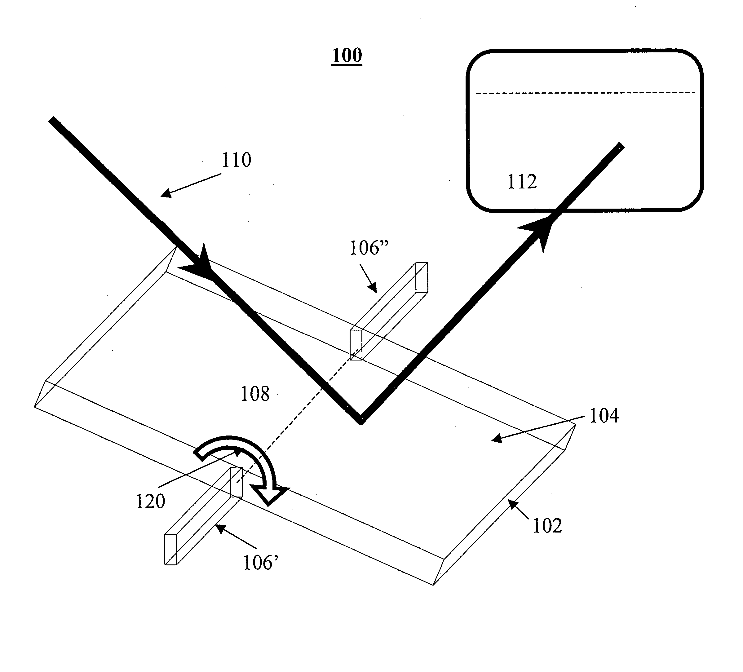
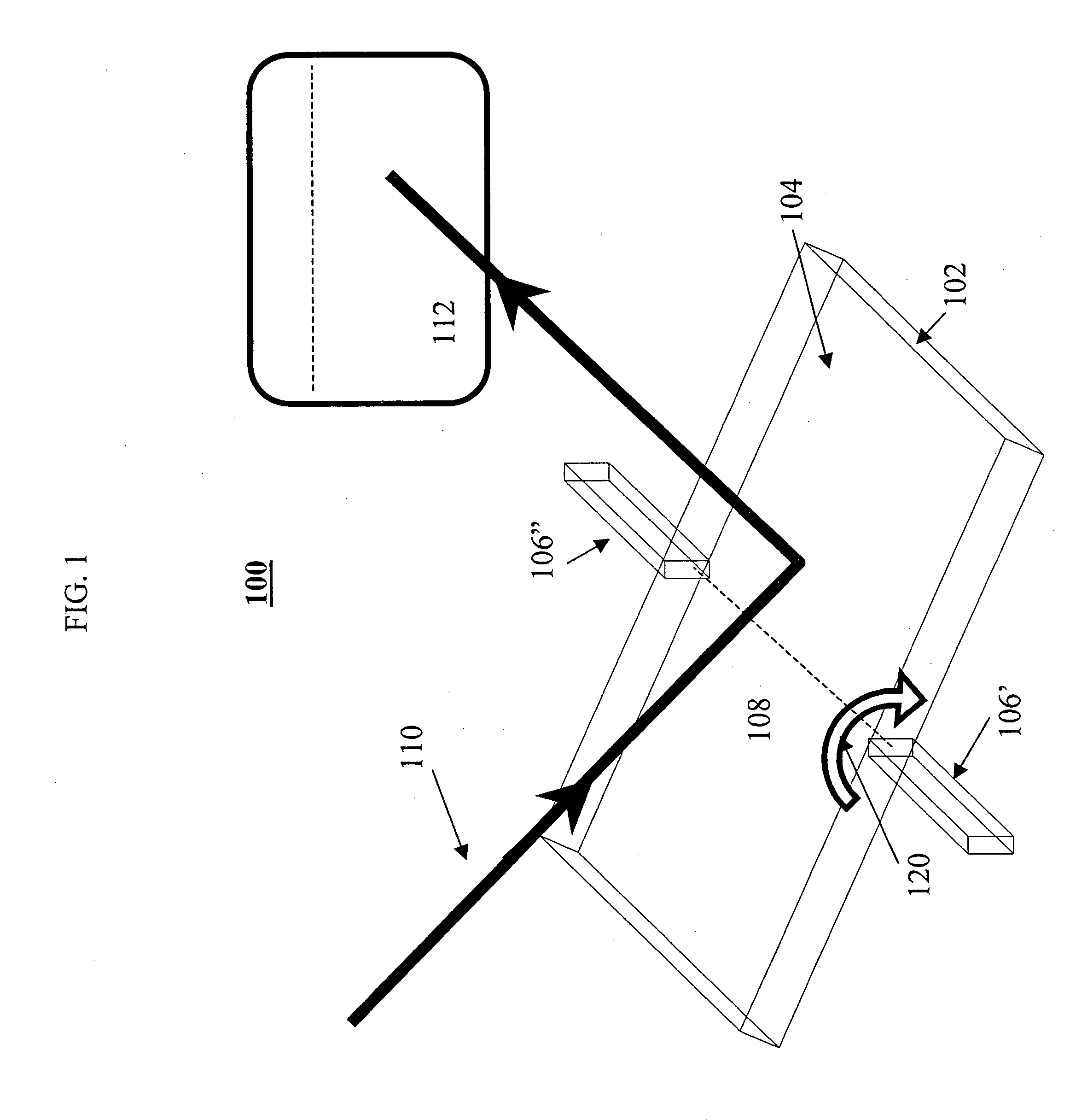
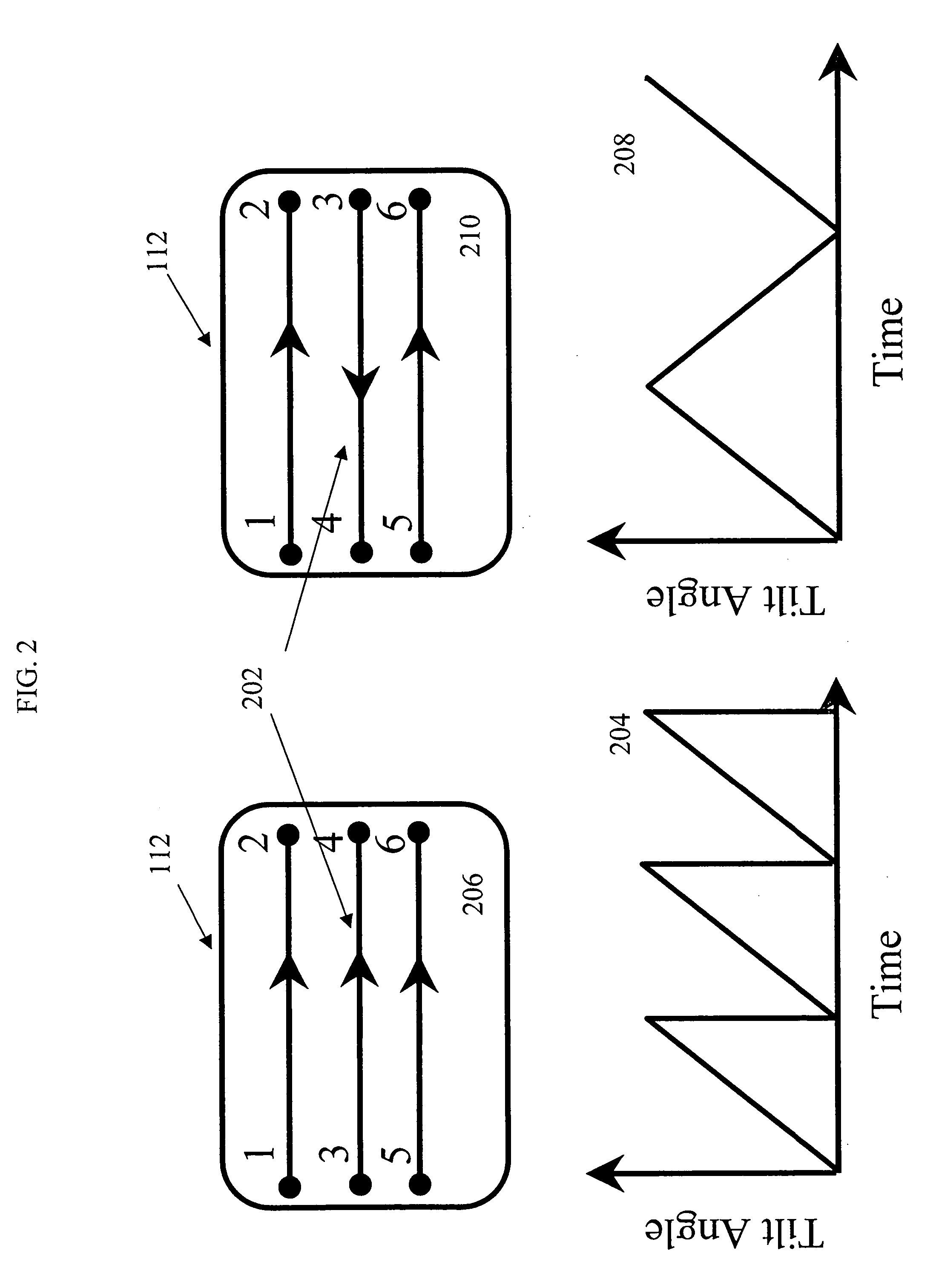
[0058] The present invention discloses a tilting bouncing mode micro-mirror that uses either an additional stiffness element (“bouncer”) or a pre-curved nonlinear stiffness element to achieve a superior scanning performance. While a bouncer such as a cantilever or beam is an element with linear stiffness, we have found inventively and advantageously that its cooperative action with other elements of the system (specifically a torsion spring) that have a different stiffness yields a combined “nonlinear stiffness element” effect. The bouncing mode uses an actuation operation mode based on a special nonlinear actuation and control principle. The “bouncing-mode” actuator that actuates the mirror is operated in the self-exciting mode and its motion is actually a limit cycle. The actuator moves the mirror in a piecewise linear trajectory. The nonlinear actuation and control principle provides a set of desirable features such as small size and weight, low power and low heat dissipation, hi...


PUM


Abstract

A MEMS apparatus for scanning an optical beam comprises a mirror operative to perform a rotational motion to a maximum rotation angle around a mirror rotation axis formed in a double active layer silicon-on-insulator (SOI) substrate. The apparatus may include a bouncing mechanism operative to provide a bouncing event and to reverse the rotational motion. The bouncing event provides the mirror with a piecewise linear response to actuation by intrinsically nonlinear electrostatic forces. In a particular embodiment, the bouncing mechanism includes a vertical comb drive stator built in the same active layer of the double active layer SOI substrate, while actuator comb drive stators are built in a different active layer.

Description

CROSS REFERENCE TO RELATED APPLICATIONS [0001] The present invention is a continuation in part of U.S. patent application Ser. No. 10 / 902,869 filed Aug. 2, 2004, which claims priority from U.S. Provisional Patent Applications Nos. 60 / 494,353 filed Aug. 12, 2003, 60 / 550,850 filed Mar. 8, 2004, and 60 / 575,248 filed Jun. 1, 2004, the contents of which are incorporated herein by reference.FIELD OF THE INVENTION [0002] The present invention relates generally to scanning micro-mirrors implemented in Micro Electro Mechanical Systems (MEMS) or Micro Opto Electro Mechanical Systems (MOEMS), and more particularly to tilting micro-mirrors used for scanning. BACKGROUND OF THE INVENTION [0003] A tilting micro-mirror is a central element in many MEMS or MOEMS devices. When used for scanning, its elements and operation principle are shown in FIG. 1. A tilting micro-mirror (or simply “mirror”) 100 comprises a generally flat plate (e.g. made of silicon) that has a reflecting surface 104. Plate 102 i...

Claims


Application Information

Patent Timeline
IPC IPC(8): G02B26/00G02B26/08G02F1/03G02F1/07
CPCG02B26/0841G02B26/00G02F1/03G02F1/07
Inventor KRYLOV, SLAVAMEDINA, MOSHEHUBER, AVIGDORLALEZAR, RONEN
Owner STMICROELECTRONICS INT NV
Why Eureka
Try Eureka