
Method and apparatus to generate an audio beam with high quality

Inactive Publication Date: 2005-10-06
SONY CORP
View PDF3 Cites 35 Cited by
  • Summary
  • Abstract
  • Description
  • Claims
  • Application Information

AI Technical Summary

Benefits of technology

[0018] Preferably, the ultrasonic carrier frequency also is broadcast through the widest aperture (or at least through a wider aperture than the ultrasonic signal derived using the high frequency audio signals). This effectively means that the equivalent modulating index for the high frequency bands is lower than it would be if the high frequency bands were transmitted using the full aperture size. Note that a small modulating index reduces the THD. As for the low frequency band, a relatively smaller amplitude modulating index may be used obtained by explicitly using a lower modulation index for signals in a low frequency band (or respective low frequency bands) than signals in the high frequency bands.

Problems solved by technology

Directional radiation at medium and low frequencies is only possible by using an array of loudspeakers having complex control mechanisms, and the resulting system has a high cost.
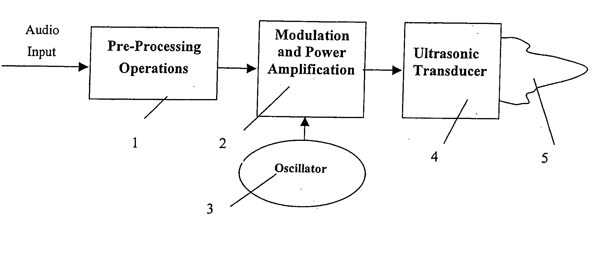
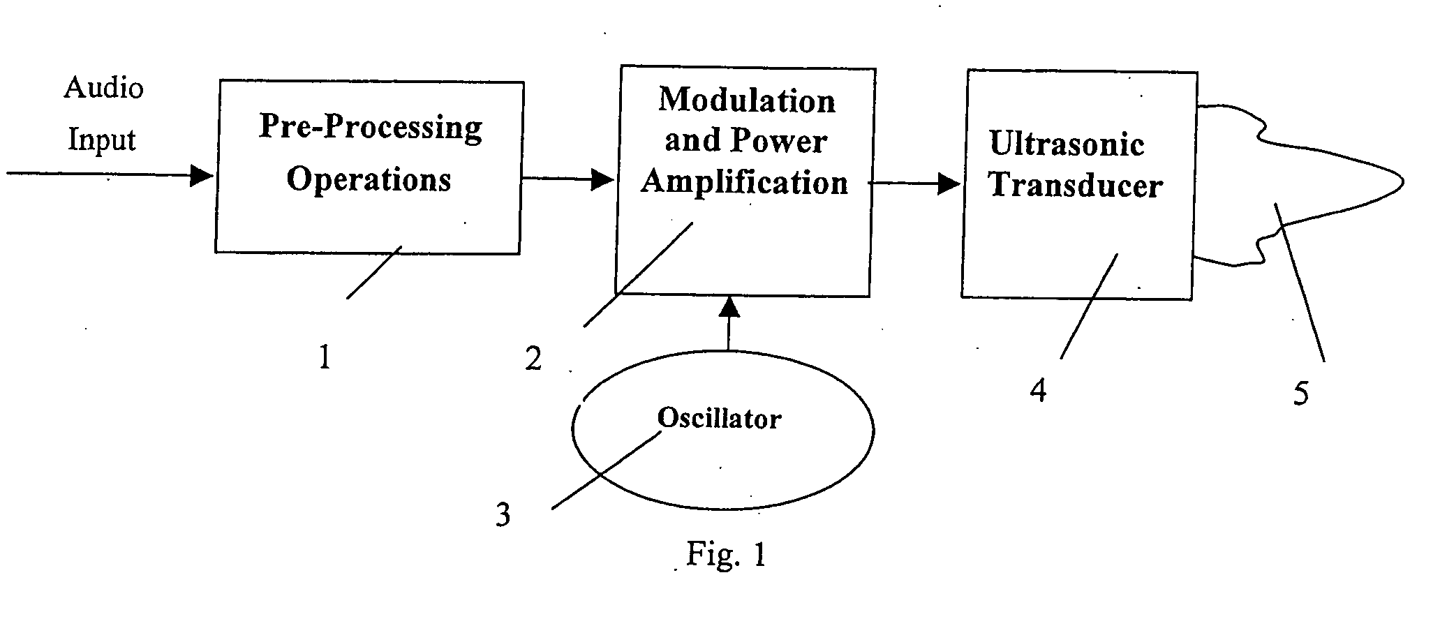
However, because the demodulating process is nonlinear, the reproduced audio signal is highly distorted unless there is appropriate pre-processing.
Such a system typically suffers from two forms of distortion.
Firstly, the frequency response is not uniform.
Secondly, the demodulating process will generate many (distortion) frequency components that are not included in the original audio signal.
However, they are neither efficient nor easy to implement in practice.
This seemingly simple pre-processing is very difficult to implement in practice.
The main difficult arises from the square-root operation.
Especially for ultrasonic transducer, it is very difficult to make a wideband and high power-efficiency transducer.
The double integration is also difficult to implement due to the −12 dB / octave amplitude weighting effect and also to the large frequency span (20˜20,000 Hz, 10 octaves) of audio signal.
Also, analog integrator is easy to saturate and difficult to debug in practice.
In summary, the simple square-root pre-processing used to compensate the distortion will not work well in practice because of the following reasons: 1) a practical transducer has a limited bandwidth which is usually not enough to transmit all the frequency components required by square-root operation, especially for high audio frequency (e.g. f>5 kHz).
2) the practical transducer frequency response is not uniform even within its pass band.
3) a wideband transducer generally has low efficiency compared with a narrow band one since it does not work near the resonant frequency point.
However, since the real feedback of the demodulated signal is not available, a model is used there to simulate the demodulating process in the air.
However, as noted, (3) is only valid under certain conditions and cannot be used as a general description of the secondary wave field.
The real performance of the method is doubtful.
Also, the iterative process is complex and requires a large amount of computation.
Thus, it is not suitable for real time implementation.
In practice, due to the non-uniform response of the circuit and transducer, it is very difficult to implement them over a wide frequency range.

Method used


Image

  • Method and apparatus to generate an audio beam with high quality
  • Method and apparatus to generate an audio beam with high quality
  • Method and apparatus to generate an audio beam with high quality

Examples


Embodiment Construction

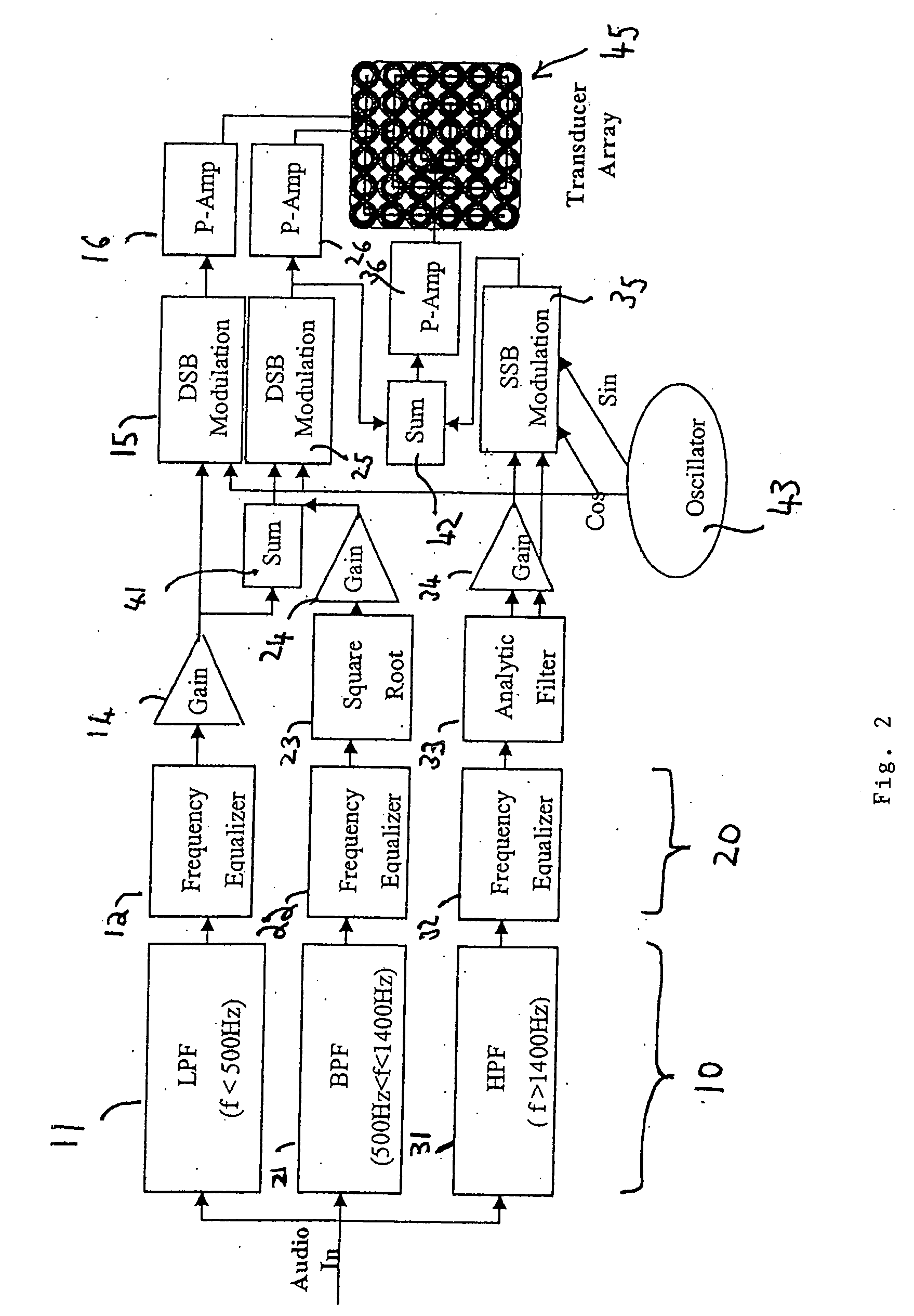
[0029] Referring to FIG. 2, an embodiment of the invention is illustrated. The processing illustrated in this figure may be implemented within the scope of the invention by either of analogue or digital processing (or any combination of the two). The following description is an example only, and in no way limits the coverage of the patent.

[0030] An audio signal is input to the embodiment from the left of the figure, and input to a filter group 10 having three filters 11, 21, 31, which respectively pass three bands (frequency ranges) of the audio signal: (1) “low band”, f11; 2) “middle band”, 500 Hz21; and (3) “high band”, f>1400 Hz, in filter 31. Of course, the frequencies which form the divisions between the bands may differ in other embodiments of the invention.

[0031] Within each band, the different frequency signals are equalized (it should be understood that the term “equalization” refers here to equalization of the amplitude components in the audio-frequency sound generated f...


PUM


Abstract

The present invention proposes a system in which an ultrasonic carrier beam is modulated using an audio input signal. The audio signal is divided into frequency bands, and that frequencies in different ones of these bands are treated differently. Specifically, different modulating schemes are used for different frequency bands. Also, different transducer aperture sizes are used for different frequency signals. Also, a further frequency equalizer is provided within each of the frequency bands. Finally, a relatively smaller amplitude modulating index (or indices) is used for signals in low frequency band(s).

Description

FIELD OF THE INVENTION [0001] The present invention relates to methods and apparatus for modifying an ultrasonic signal such that, when transmitted through a transducer, it generates an ultrasonic beam modulated with an audio signal, so that the audio signal is reproduced in air. BACKGROUND OF THE INVENTION [0002] The acoustic field generated by conventional loudspeaker is not directional especially for low frequency signals. Directional radiation at medium and low frequencies is only possible by using an array of loudspeakers having complex control mechanisms, and the resulting system has a high cost. [0003] However, it is well known that a highly directional ultrasonic beam can be generated relatively easily. It is further known to modulate an ultrasonic wave such that it contains two ultrasonic frequency components differing by an audio frequency, and transmit the modulated ultrasonic wave into air as a narrow beam. Nonlinear effects of the air cause the two component signals to ...

Claims


Application Information

Patent Timeline
IPC IPC(8): H04R1/26H04R3/00H04R1/40H04R3/04H04R3/14H04R17/00
CPCH04R1/26H04R3/04H04R2217/03H04R17/00H04R3/14
Inventor SUN, XIAOBINGOKADA, KANZO
Owner SONY CORP
Learn More