Adsorber for adsorbing hydrocarbon vapors from return flows through an intake tract of an internal combustion engine

a technology of hydrocarbon vapor and return flow, which is applied in the direction of combustion-air/fuel-air treatment, separation process, filtration separation, etc., can solve the problems of increasing the flow resistance in the intake tract, increasing complexity, and risk of individual fragments falling off, so as to facilitate the replacement facilitate the arrangement of the element. , the effect of increasing the stability of the adsorption elemen

Inactive Publication Date: 2005-10-13
MANN HUMMEL GMBH
View PDF15 Cites 24 Cited by
  • Summary
  • Abstract
  • Description
  • Claims
  • Application Information

AI Technical Summary

Benefits of technology

[0022] In accordance with another advantageous embodiment, a supporting layer is arranged around the adsorption element enclosing all the layered layers. The supporting layer may be formed, for example, by layers of the spacer element that are cut oversized and are coiled around the periphery of the adsorption element. The filter element may also be enclosed by a housing made of plastic or metal, surrounding the element directly above the layers or comprising an intermediate supporting layer. For example, a gasket which ensures a reliable separation between the oncoming flow side and the outflow side may be mounted on this filter housing. A filter housing or a supporting layer surrounding the element imparts additional stability to the adsorption element. The adsorption element may be designed as a lifetime component under the usual use conditions. However, this design of the element facilitates replacement of the adsorption element in an installation space provided for this purpose, e.g., in an air filter element or as an inline arrangement on an air duct connection. In the case of an inline arrangement of the adsorption element, this also facilitates arranging the element in a branch of the air guidance system, where it can be triggered separately by a valve control. This arrangement makes it possible to activate and/or deactivate the element in different operating phases of the internal combustion engine, in which case the adsorption element must be activated when the engine is at a standstill.
[0023] Another advantageous embodiment of the adsorption element is deriv

Problems solved by technology

One disadvantage of this type of extruded or pressed monolith adsorption element is that they are preferably manufactured from powdered activated carbon and a binder and therefore have a brittlen

Method used


Image

  • Adsorber for adsorbing hydrocarbon vapors from return flows through an intake tract of an internal combustion engine
  • Adsorber for adsorbing hydrocarbon vapors from return flows through an intake tract of an internal combustion engine
  • Adsorber for adsorbing hydrocarbon vapors from return flows through an intake tract of an internal combustion engine

Examples


Embodiment Construction

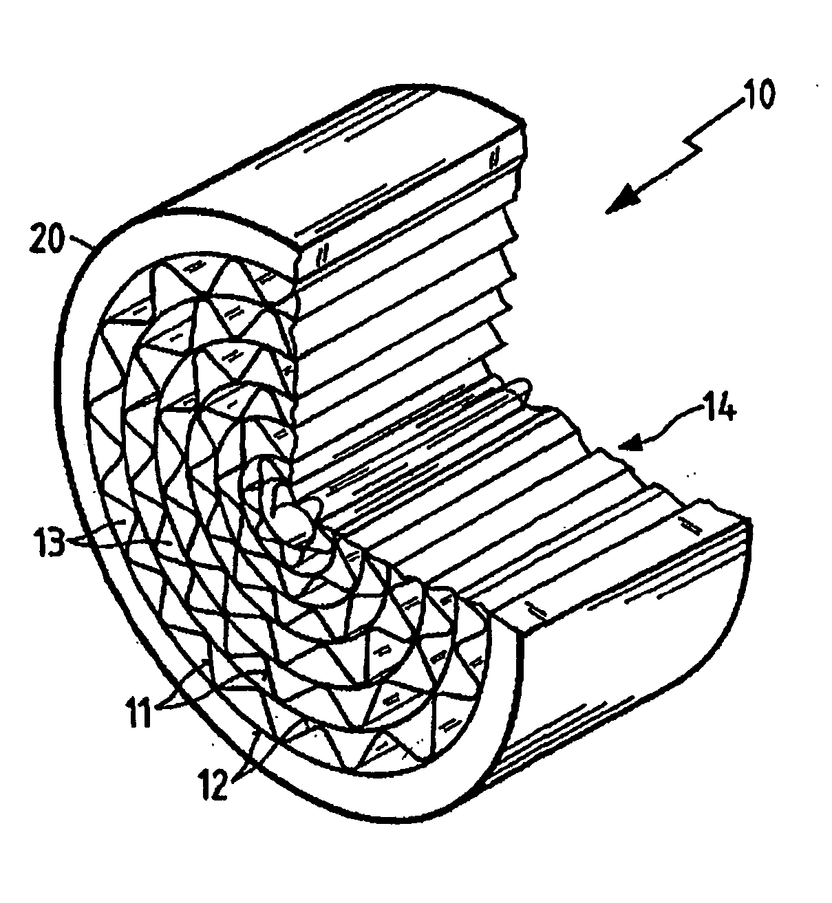
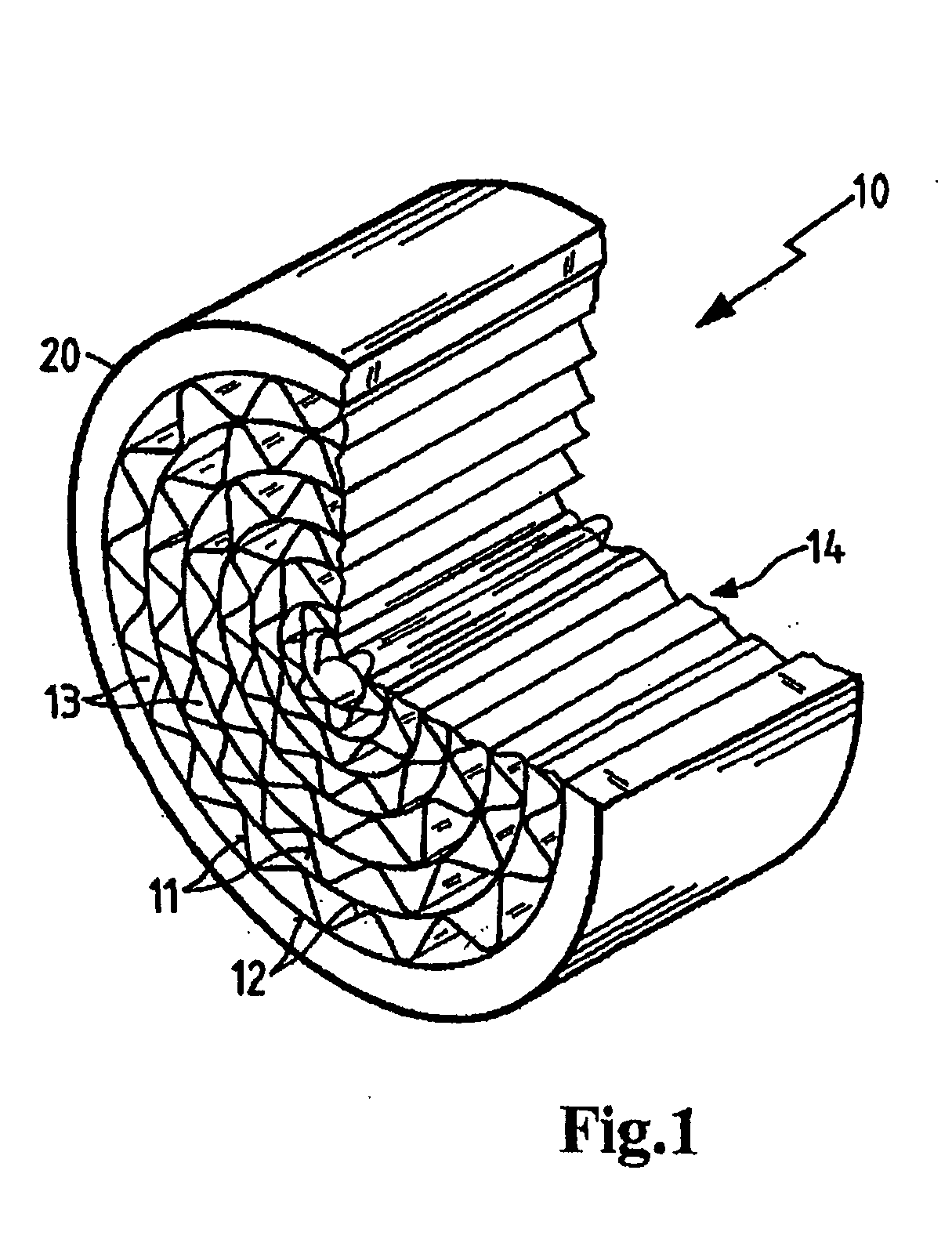
[0030]FIG. 1 shows an adsorption element 10 which comprises an adsorption layer 12 and a spacer element 11. In the illustrative embodiment shown here, the spacer element 11 is constructed with pleating and / or corrugations, with one layer of the spacer element 11 and the adsorption layer 12 being rolled up from the inside to the outside. The corrugation of the spacer element 11 results in free-flow channels 13 between the adsorption layer 12 and the spacer element 11. The gas stream thus may flow through the adsorption element 10 between the end faces 14 without having to flow through a layer of material. Instead, in this embodiment it flows directly along an adsorption layer 12.

[0031] The shape of the adsorption element 10 need not necessarily be round because of being rolled up, but instead it may also be oval or designed to approximate a polygon. The contact surfaces between the adsorption layer 12 and the spacer element 11 may be joined together adhesively or may be simply clamp...


PUM

PropertyMeasurementUnit
Temperatureaaaaaaaaaa
Adsorption capacityaaaaaaaaaa
Adsorption entropyaaaaaaaaaa

Abstract

An adsorption element for adsorbing gases and vapors from the gas atmosphere in a gas stream in an intake tract of an internal combustion engine, in which the gas atmosphere is present in a flow cross section of the intake tract. The adsorption element has free-flow channels through which the gas stream is passed. The adsorption element includes at least one adsorption layer, and the free-flow channels are formed by at least one spacer element, and the spacer element is arranged between adsorption layers.

Description

BACKGROUND OF THE INVENTION [0001] This invention relates to an adsorption element for adsorption of gases and vapors from the gas atmosphere in the gas stream of the intake tract of an internal combustion engine, and to a method for adsorbing gases such as hydrocarbon vapors in return flows from an internal combustion engine. [0002] Adsorption elements are used for air intake systems of internal combustion engines, for example. The adsorption elements here have the function of adsorbing hydrocarbons which threaten to escape from the intake system after the engine is shut down. When the engine is subsequently operated again, the hydrocarbons are again desorbed from the adsorption element into the air intake stream and are then burned in the engine which restores the capacity of the adsorption element. [0003] For example, U.S. Pat. No. 5,914,294 (=CA 2,367,031) discloses a monolith which adsorbs chemical constituents from a gas stream. This is achieved by bringing the gas stream into...

Claims


Application Information

Patent Timeline
IPC IPC(8): B01D53/04F02M35/10F02M25/08B01D46/52B01D39/20B01J20/28F02M35/04F02M35/02
CPCB01D53/0415B01D53/0446B01D2239/0407B01D2239/0604B01D2253/102B01D2253/108B01D2253/25B01D2253/342B01D2257/702B01D2258/01B01D2259/40081B01D2259/40086B01D2259/4516B01D2259/4566B01J20/28033B01J20/2804B01J20/28052F02M25/0854F02M35/02F02M35/10019F02M35/10222
Inventor SOHNEMANN, JENS
Owner MANN HUMMEL GMBH
Why Eureka
Try Eureka