Apparatus and method for retarding an engine with an exhaust brake and a compression release brake

a technology of compression release brake and exhaust brake, which is applied in the direction of engine components, valve details, valve control, etc., can solve the problems of engine braling or retarding, power loss, and failure to recover compression energy, so as to enhance the operation enhance the braking effect of the compression release brak

Inactive Publication Date: 2005-10-13
JENARA ENTERPRISES
View PDF7 Cites 16 Cited by
  • Summary
  • Abstract
  • Description
  • Claims
  • Application Information

AI Technical Summary

Benefits of technology

[0011] According to one aspect of the invention, an apparatus for retarding an engine has a cylinder with an exhaust valve, an intake valve, an intake stroke, an exhaust stroke, a compression stroke and an expansion stroke. The apparatus includes an exhaust brake and a compression release brake. The exhaust brake includes a variable exhaust restrictor, a pressure sensor for sensing pressure of exhaust gases, a controller operatively connected to the pressure sensor and to the exhaust restrictor so as to adjust opening of the exhaust restrictor during operation of the apparatus so exhaust pressure is sufficient to cause exhaust valve float prior to bottom dead center of intake strokes of the cylinder, thereby enhancing operation of the compression release brake.
[0012] According to another aspect of the invention, there is a method for retarding an engine apparatus having a cylinder with an exhaust valve, an intake valve, an intake stroke, an exhaust stroke, a compression stroke and an expansion stroke. The apparatus includes an exhaust brake and a compression release brake. The exhaust brake includes a variable exhaust restrictor, a pressure sensor for sensing pressure of exhaust gases, a controller operatively connected to the pressure sensor and to the exhaust restrictor. The controller adjusts opening of the exhaust restrictor during operation of the apparatus so exhaust pressure is sufficient to cause exhaust valve float prior to bottom dead center of intake strokes of the cylinder, thereby enhancing operation of the compression release brake.
[0013] The invention offers significant advantages over the prior art. Compared to a conventional compression release brake, it does not require the expensive hardware required to open exhaust valves against the extremely high load of the compressed cylinder charge. However, at low engine speeds engine braking is enhanced because the exhaust restrictor is closed a sufficient amount to maintain a pressure which causes exhaust valve float, and thereby enhances operation of the bleeder brake at low engine speeds as well.
[0014] Moreover the invention provides a low-cost engine braking system which can be integrated into overall engine design. Mechanical and thermal components of the engine are not overloaded since the exhaust restrictor can be adjusted below maximum temperature and pressure limits.
[0015] Finally, by regulating exhaust pressure, the system ensures relatively quiet brake operation compared with conventional compression release brakes. Thus engine braking systems according to the invention may be utilized in environment sensitive to noise pollution, such as urban areas.

Problems solved by technology

This creates a blow-down of the compressed cylinder gas and the energy used for compression is not reclaimed.
The result is engine braling, or retarding, power.
This type of brake has substantial cost associated with the hardware required to open the exhaust valves against the extremely high load of the compressed cylinder charge.
Also, the sudden release of the highly compressed gas causes high noise levels.
This means that engine brakes cannot be used in certain areas, typically urban areas, leading to a potential safety hazard.
Braking power may fall off sharply at reduced engine speeds, when the turbocharger slows down and delivers less air to the cylinder.
The restriction is simply insufficient to be effective at lower engine speeds.

Method used


Image

  • Apparatus and method for retarding an engine with an exhaust brake and a compression release brake
  • Apparatus and method for retarding an engine with an exhaust brake and a compression release brake
  • Apparatus and method for retarding an engine with an exhaust brake and a compression release brake

Examples


Embodiment Construction

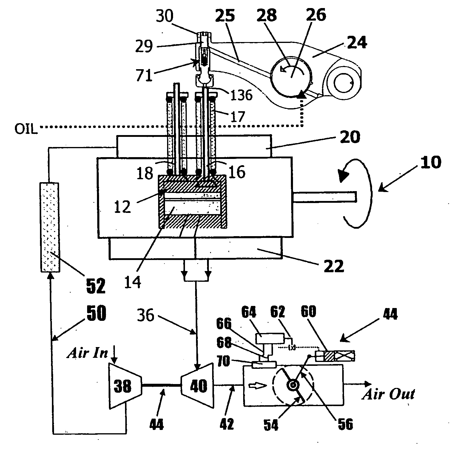
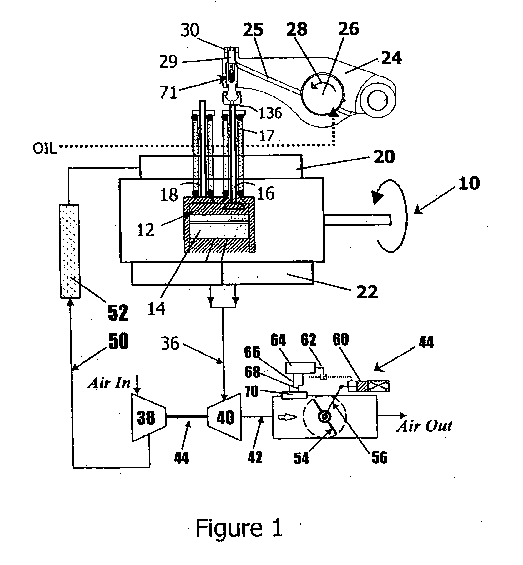
[0022] Referring to the drawings and first to FIG. 1, this shows an internal combustion engine 10, a diesel engine in this instance, equipped with a plurality of cylinders, only cylinder 12 being shown for simplicity. Each cylinder is provided with a piston 14 which reciprocates therein. Each cylinder has an exhaust valve 16 and an intake valve 18. Each cylinder may have more than one intake valve and / or exhaust valve, but again only one of each is shown for simplicity. The engine also has an intake manifold 20 and an exhaust manifold 22.

[0023] In the conventional manner exhaust valve 16 is opened by rotation of rocker arm 24 about rocker arm shaft 26 in the direction indicated by arrow 28. The rocker arm is provided with an adjustment screw 29 capable of adjusting clearance between the rocker arm and the valve.

[0024] The exhaust manifold 22 is connected to a turbocharger 34 by an exhaust conduit 36. The turbocharger includes a compressor 38 and a turbine 40. The exhaust gases exi...


PUM


Abstract

An apparatus and method for retarding an engine having a cylinder with an exhaust valve, an intake valve, an intake stroke, an exhaust stroke, a compression stroke and an expansion stroke. The apparatus includes an exhaust brake and a compression release brake. The exhaust brake includes a variable exhaust restrictor, a pressure sensor for sensing pressure of exhaust gases and a controller operatively connected to the pressure sensor and to the exhaust restrictor. Opening of the exhaust restrictor is adjusted during operation of the apparatus so exhaust pressure is sufficient to cause exhaust valve float prior to bottom dead center of intake strokes of the cylinder, thereby enhancing operation of the compression release brake.

Description

BACKGROUND OF THE INVENTION [0001] This invention relates to methods and apparatuses for retarding engines and, in particular, to compression release brakes, such as bleeder brakes, and to exhaust brakes. [0002] Conventional compression release brakes retard engines by opening the exhaust valves just prior to Top Dead Center (TDC) of the compression stroke. This creates a blow-down of the compressed cylinder gas and the energy used for compression is not reclaimed. The result is engine braling, or retarding, power. This type of brake has substantial cost associated with the hardware required to open the exhaust valves against the extremely high load of the compressed cylinder charge. The valve train components must be designed and manufactured to operate reliably at high mechanical loading. Also, the sudden release of the highly compressed gas causes high noise levels. This means that engine brakes cannot be used in certain areas, typically urban areas, leading to a potential safety...

Claims


Application Information

Patent Timeline
Patent Type & Authority Applications(United States)
IPC IPC(8): F01L13/06F02D9/06F02D13/04
CPCF01L13/06F01L2760/00F02D9/06F02D13/04
Inventor ISRAEL, MARK A.HARTLEY, JOHN P.MENEELY, VINCENT A.
Owner JENARA ENTERPRISES
Why Eureka
Try Eureka