

Materials for injecting or transporting holes and organic electroluminescence devices using the same
a technology of organic electroluminescence and material, which is applied in the direction of conveyors, discharge tubes luminescnet screens, other domestic articles, etc., can solve the problems of insufficient luminance characteristics, lifespan and durability of devices for practical use, and the difficulty of realizing full color, etc., to achieve the effect of improving luminous efficiency and lifespan, reducing energy gap, and limited efficiency
- Summary
- Abstract
- Description
- Claims
- Application Information
AI Technical Summary
Benefits of technology
Problems solved by technology
Method used
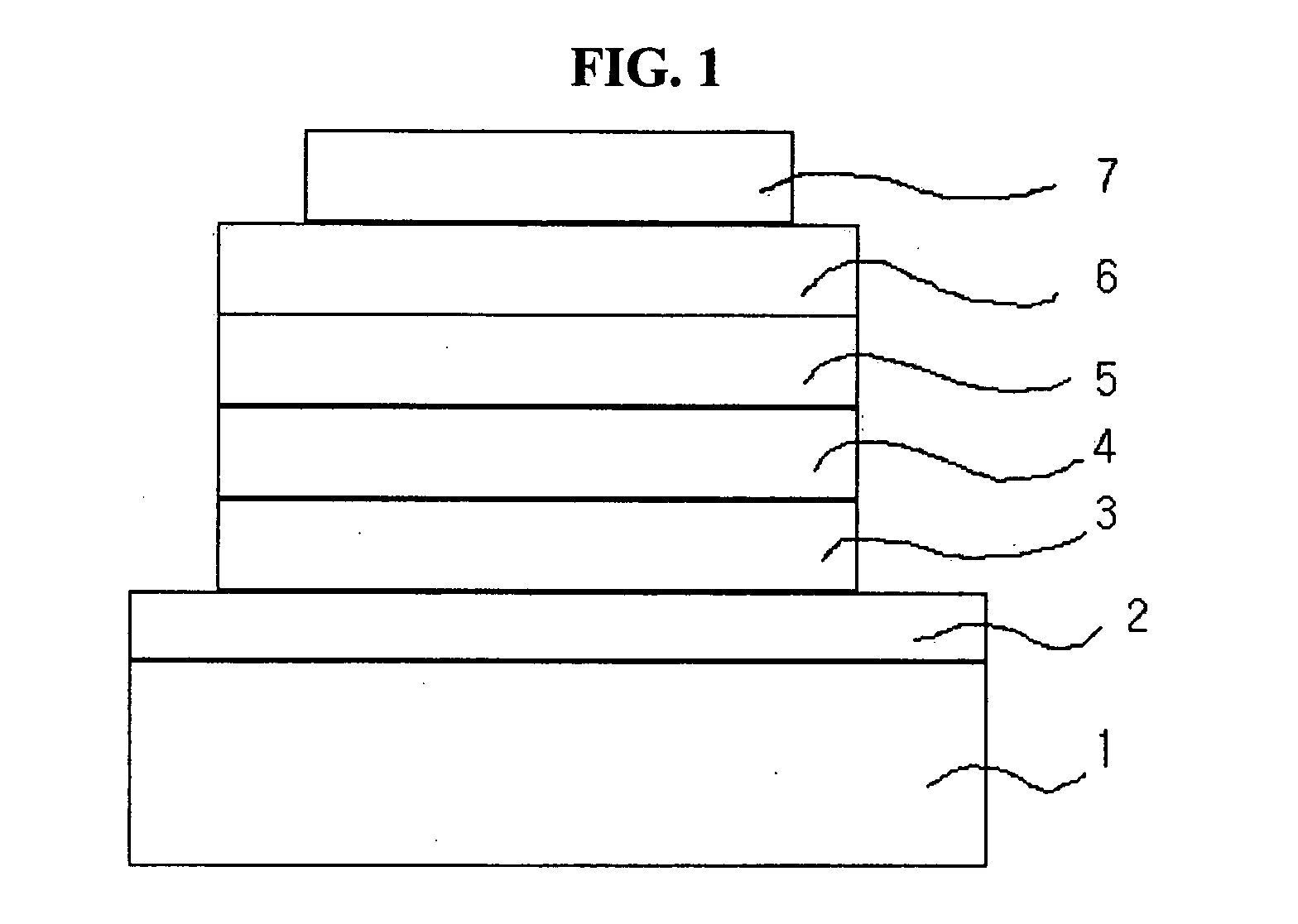
Image

Examples
preparation example 1
Preparation of the Starting Material Represented by Formula a
[0063] Carbazole (5.00 g, 29,9 mmol), 1-bromo-4-iodobenzene (9.30 g, 32.9 mmol), K2CO3 (16.5 g, 120 mmol), Cu (3.80 g, 59.8 mmol) and 18-crown-6 (0.40 g, 1.49 mmol) were refluxed in 50 ml of o-dichlorobenzene for 15 hours. After the completion of the reaction, the reaction mixture was cooled to room temperature and the precipitate was filtered off. The filtrate was washed with water three times, dried over MgSO4 and concentrated under reduced pressure. The reaction mixture was purified by column chromatography to obtain the compound represented by formula a as starting material (5.85 g, 61%). 1H NMR (300 MHz, CDCl3) 8.13-8.11 (d, 2H), 7.71-7.69 (d, 2H), 7.44-7.21 (m, 8H); MS [M+H] 322.
preparation example 2
Preparation of the Starting Material Represented by Formula b
[0064] Carbazole (5.00 g, 29,9 mmol), 1-bromo-3-iodobenzene (9.30 g, 32.9 mmol), K2CO3 (16.5 g, 120 mmol), Cu (3.80 g, 59.8 mmol) and 18-crown-6 (0.40 g, 1.49 mmol) were refluxed in 50 ml of o-dichlorobenzene for 15 hours. After the completion of the reaction, the reaction mixture was cooled to room temperature and the precipitate was filtered off. The filtrate was washed with water three times, dried over MgSO4 and concentrated under reduced pressure. The reaction mixture was purified by column chromatography to obtain the compound represented by formula b as starting material (5.85 g, 61%). MS [M+H] 322.
preparation example 3
Preparation of the Starting Material Represented by Formula c
[0065] The starting material represented by formula a (1.50 g, 4.66 mmol) was dissolved in dimethylformaide (DMF, 20 ml) and N-bromosuccinimide (NBS, 1.82 g, 10.2 mmol) was added thereto. The reaction mixture was reacted at 50-60° C. for 2 hours and water (15 ml) was added thereto. The resultant precipitate was filtered, washed with water and then recrystallized in dichloromethane / n-hexane to obtain the compound represented by formula c as starting material (1.93 g, 86%). 1H NMR (300 MHz, CDCl3) 8.17 (s, 2H), 7.75-7.74 (d, 2H), 7.51-7.48 (d, 2H), 7.38-7.35 (d, 2H), 7.22-7.19 (d, 2H); MS [M+H] 478.
PUM
| Property | Measurement | Unit |
|---|---|---|
| Transport properties | aaaaa | aaaaa |
| Light | aaaaa | aaaaa |
| Thermal stability | aaaaa | aaaaa |
Abstract
Description
Claims
Application Information