Method and apparatus for automotive radar sensor

a radar sensor and automotive technology, applied in the field of automotive electronic systems and methods, can solve the problems of limiting the ability of target identification and classification, poor level of target detection and discrimination for radar imaging applications in typical sensors, and limiting target identification and classification capabilities, so as to reduce overall costs, increase imaging capability, and high signal-to-noise ratio

Inactive Publication Date: 2005-10-13
GHZ TR CORP
View PDF3 Cites 158 Cited by
  • Summary
  • Abstract
  • Description
  • Claims
  • Application Information

AI Technical Summary

Benefits of technology

[0006] Methods and apparatus are presented which reduce the overall cost and increase the imaging capability for medium and long range automotive radar sensing applications through the combination of a high signal-to-noise ratio and wide dynamic range radar waveform and architecture, antenna arrangement, and a low-cost packaging and interconnection method. In accordance with aspects of the present invention, one way a high signal-to-noise ratio and wide dynamic range imaging radar with reduced cost can be achieved is through the combination of a pulsed stepped-frequency-continuous-wave waveform and electrically beam-switched radar architecture, utilizing a planar package containing high-frequency integrated circuits as well as integrated high-frequency waveguide coupling ports, coupled to a multi-beam waveguide-fed twist-reflector narrow beam-width antenna. Other methods and apparatus are presented.

Problems solved by technology

However, these systems are very limited in their ability to resolve multiple target returns within this beam-width area and thus provide information as target point positions rather than images of distributed target boundaries, severely limiting target identification and classification capability.
Also, due to the low gain of the relatively wide transmit / receive beam-width, and relatively low average transmitted power and / or low dynamic range of the typical radar waveform and architecture used, the level of target detection and discrimination for radar imaging applications is poor in typical sensors.
Furthermore, the manufacturing cost associated with typical radar sensors is high due to the use of expensive metal hybrid modules and hybrid assembly techniques, mechanically scanned antennas, millimeter-wave packages with high-frequency connections to exotic printed circuit boards, and / or the use of multiple, expensive millimeter-wave components.

Method used


Image

  • Method and apparatus for automotive radar sensor
  • Method and apparatus for automotive radar sensor
  • Method and apparatus for automotive radar sensor

Examples


Embodiment Construction

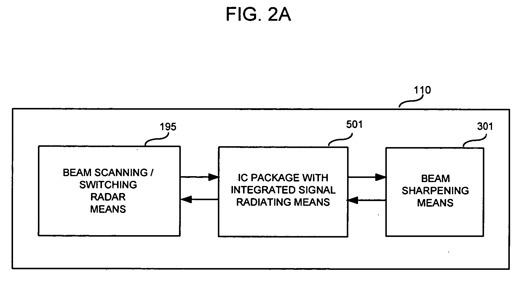
[0204] One embodiment of the generalized diagram shown in FIG. 2A illustrates the features of an integrated radar imaging sensor 110 capable of producing high signal-to-noise ratio and wide dynamic range images of distributed targets where high resolution target boundaries, not just single point returns from targets, can be determined in a low-cost, mass-production capable unit, in accordance with aspects of the present invention. A beam scanning, switching radar means 195 is coupled with an integrated circuit (IC) package having integrated signal radiating means 501, which is then coupled to a transmit / receive beam sharpening means 301 for transmission and reception of a narrow electromagnetic signal beam. Signal radiating means are defined as high-frequency structures used to electro-magnetically couple one or a plurality of signals to and / or from the package using a solderless connection. Examples of signal radiating means can be, but are not limited to, patch antennas, slot ante...


PUM


Abstract

Methods and apparatus are presented which reduce the overall cost and increase the imaging capability for medium and long range automotive radar sensing applications through the combination of a high signal-to-noise ratio and wide dynamic range radar waveform and architecture, antenna arrangement, and a low cost packaging and interconnection method. In accordance with aspects of the present invention, one way a high signal-to-noise ratio and wide dynamic range imaging radar with reduced cost can be achieved is through the combination of a pulsed stepped-frequency-continuous-wave waveform and electrically beam-switched radar architecture, utilizing a planar package containing high-frequency integrated circuits as well as integrated high-frequency waveguide coupling ports, coupled to a multi-beam waveguide-fed twist-reflector narrow beam-width antenna. Other methods and apparatus are presented.

Description

BACKGROUND OF THE INVENTION [0001] 1. Technical Field of the Invention [0002] The subject matter disclosed generally relates to the field of automotive electronic systems and methods. More specifically, the subject matter disclosed relates to radar sensor arrangements that allow cost reduction and increased utility for automotive radar collision avoidance and driver aid applications. [0003] 2. Background of Related Art [0004] To facilitate mass deployment of automotive radar sensors, reducing the total system cost per vehicle without compromising the capability, performance, or reliability of the system is desirable. Furthermore, increasing the capability, utility, and applications of the sensor, especially in the area of safety, can enhance the value and promote deployment. Automotive medium to long range sensing applications typically aim to provide information relating to objects in a certain angular area in-front of, or behind of, the equipped vehicle with high resolution object...

Claims


Application Information

Patent Timeline
Patent Type & Authority Applications(United States)
IPC IPC(8): G01S13/34G01S13/24G01S13/93G01S13/08H01Q1/32H01Q21/08G01S7/35G01S7/28G01S7/03H01Q15/24H01Q1/38G01S13/28H01Q21/00G01S13/931
CPCG01S7/032G01S7/354G01S13/08G01S13/24G01S13/282G01S13/347G01S13/931G01S2007/356G01S2007/358H01L2224/73253H01L2924/01057H01L2924/01078H01L2924/01079H01L2924/09701H01L2924/16152H01L2924/16153H01Q1/3233H01Q1/38H01Q15/248H01Q21/0093H01Q21/08H01L2924/01019H01L2924/01066H01L2924/01068H01L2924/01322H01L2224/32225H01L2224/32245H01L2224/73204H01L2924/16251H01L2924/19107H01L2224/48091H01L2924/00014H01L2224/16225H01L2224/48227H01L2224/73265H01L2924/00H01L2224/05554G01S7/358G01S7/356
Inventor BONTHRON, ANDREW J.
Owner GHZ TR CORP
Why Eureka
Try Eureka