
Electrical over stress robustness

Inactive Publication Date: 2005-10-13
AVAGO TECH INT SALES PTE LTD
View PDF9 Cites 26 Cited by
  • Summary
  • Abstract
  • Description
  • Claims
  • Application Information

AI Technical Summary

Benefits of technology

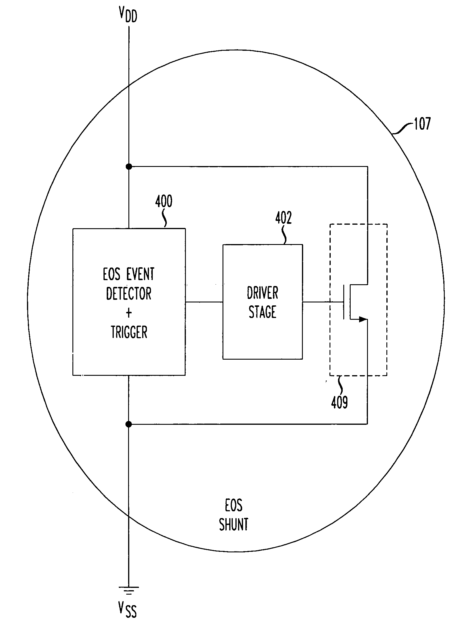
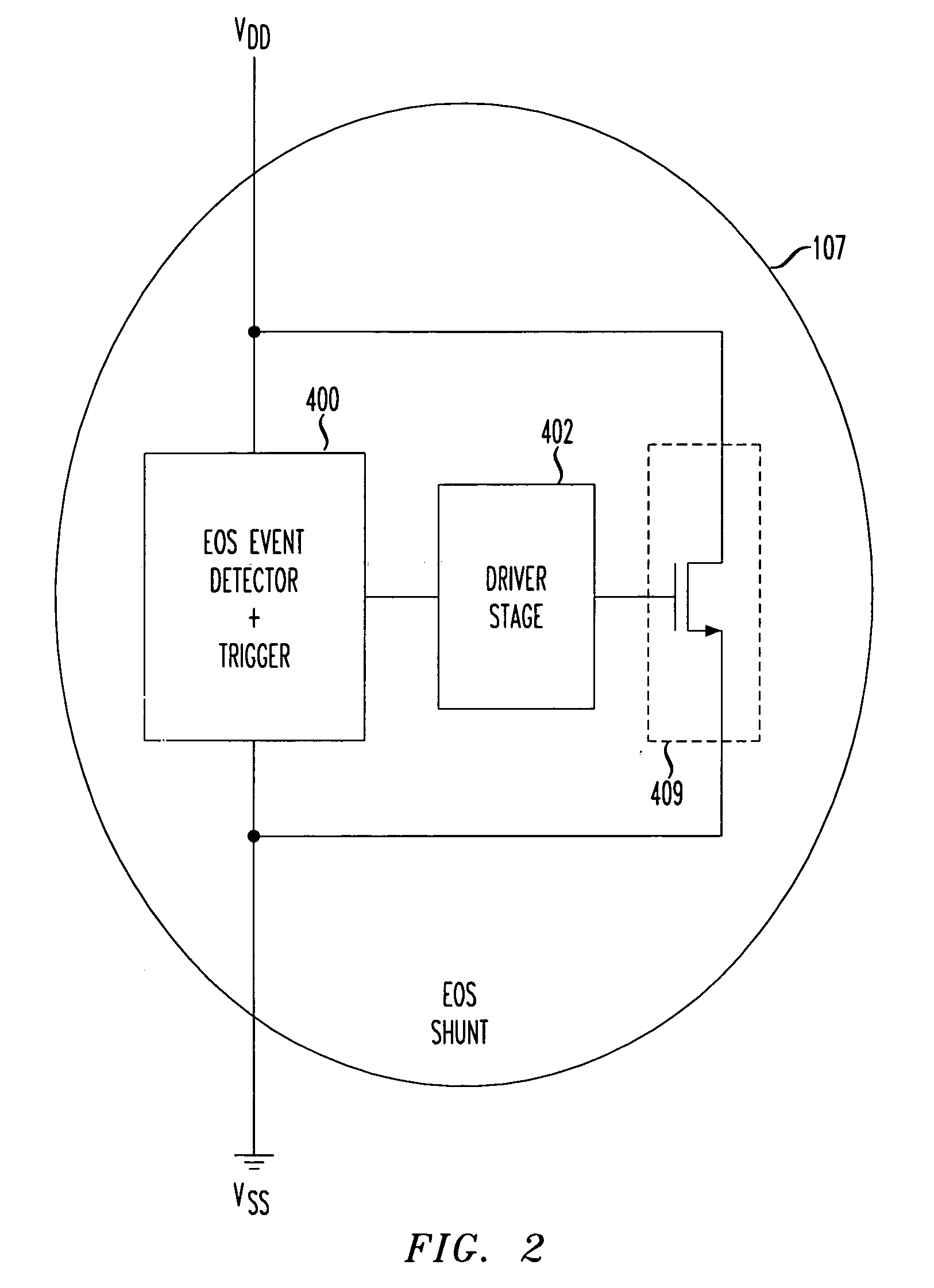
[0020] In accordance with the principles of the present invention, an integrated circuit including an electrical over stress shunt comprises a voltage threshold detector to detect an electrical over stress event wherein a potential is measured between a higher voltage rail such as a power rail and a lower voltage rail such as a ground rail in excess of a predetermined voltage. A switchable low resistance path is implemented between the power rail and the ground rail. The low resistance path is adapted to be switched ON for the duration of the electrical over stress event.
[0021] In accordance with another aspect of the present invention, a power distribution system in an integrated circuit comprises a power rail, a ground rail, and an electrical over stress shunt. The EOS shunt is connected between the power rail and the ground rail. The electrical over str

Problems solved by technology

However, as the inventors of the present application have appreciated, Firewire devices are prone to electrical over stress damage.
However, Firewire cables are not designed to ensure grounded contact before other electrical connections are made.
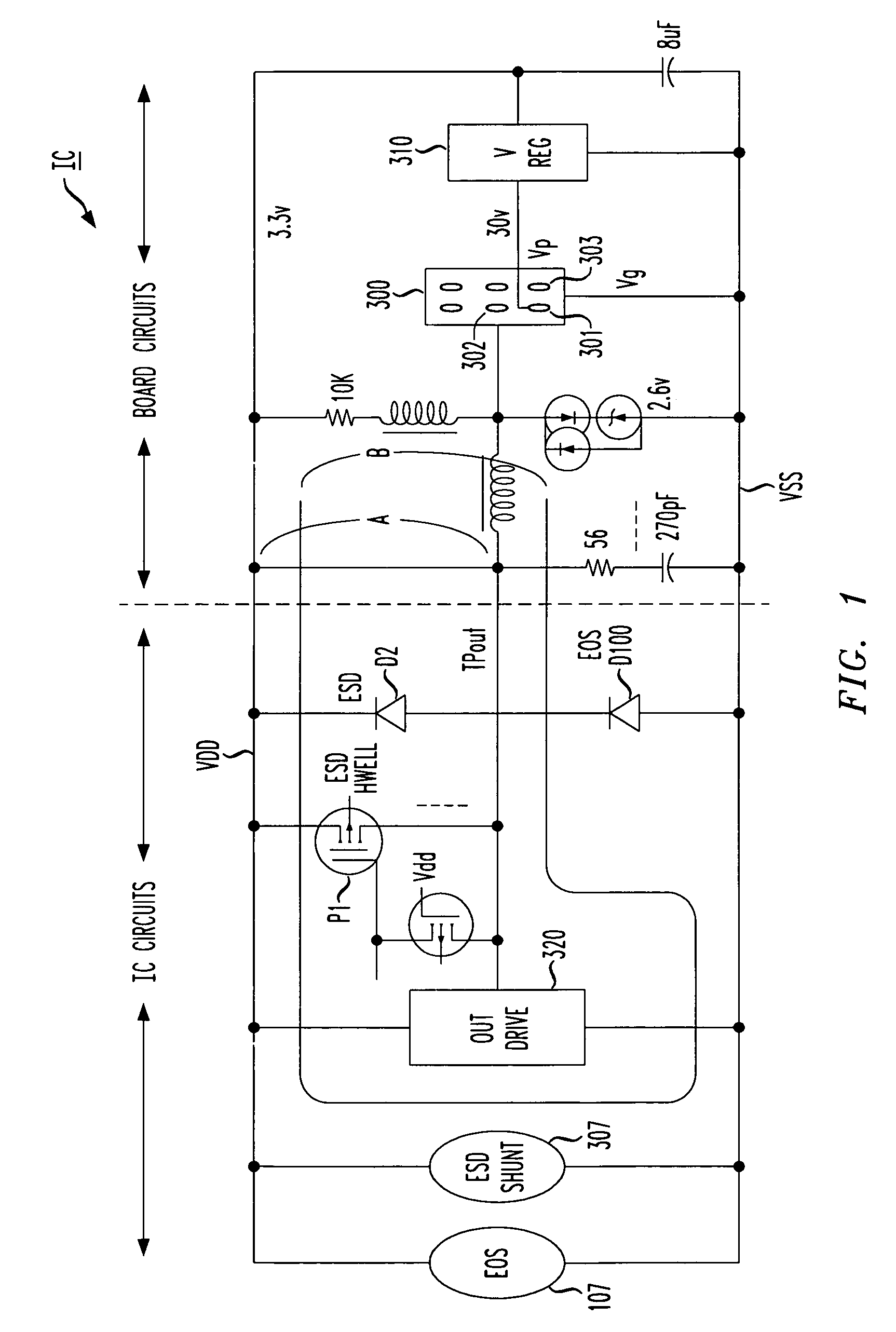
FIG. 6 shows a conventional Firewire circuit that is susceptible to damage due to electrical over stress conditions.
Although cable connections can be performed quickly, EOS conditions nevertheless cause serious damage not solved by conventional ESD protection.
Eventually, damage may also occur in the OUT drive circuits 320 themselves.
Conventional electrostatic discharge shunts or clamps 307 are designed to handle an ESD event, and are not suitable for alleviating the potential for damage resulting from a typical EOS event.
However, ESD is typically a very short term event, whereas electrical over stress in comparison can be a much longer term event.
Thus, the design of the now well-standardized Firewire cable cannot easily be changed without making obsolete many, many devices already in the marketplace.

Method used


Image

  • Electrical over stress robustness
  • Electrical over stress robustness
  • Electrical over stress robustness

Examples


Embodiment Construction

[0030] The present invention provides protection for integrated circuits against electrical surges resulting from electrical over stress type conditions, e.g., when interfacing to a circuit including power connections electrical over stress can be improved by forcing the large currents that occur as a result of a late system ground to flow through a clamp implemented between the power rail Vdd and the ground rail Vss. The electrical over stress protection is triggered by a predetermined voltage threshold, and thus is activated for as long as the electrical over stress condition exists. ESD protection may additionally be implemented, but ESD protection is typically triggered based on an RC time constant that turns the ESD protection off after no more than about 2 microseconds. An ESD shunt will not protect integrated circuits from electrical over stress. EOS protection using an EOS shunt in accordance with the principles of the present invention remains activated by a voltage thresho...


PUM


Abstract

Protection is provided against electrical surges resulting from Electrical Over Stress conditions, e.g., when interfacing circuits with powered connections. An EOS shunt is activated for as long as the EOS condition exists. EOS protection using an EOS shunt in accordance with the principles of the present invention remains activated by a voltage threshold trigger as long as necessary. In a disclosed embodiment, an EOS shunt includes a voltage threshold detector that detects a voltage on a power bus with respect to a ground rail exceeding a predetermined amount, e.g., 5 volts in a device powered at 3.3 volts. During the EOS event, a path between power and ground comprising a transistor is turned on.

Description

BACKGROUND OF THE INVENTION [0001] 1. Field of the Invention [0002] This invention relates to integrated circuits(ICs). More particularly, it relates to a design technique and method to better protect electrical circuits such as an integrated circuit from electrical over stress (EOS) damage, particularly useful in the design of a IEEE 802A “Firewire” high speed serial interface. [0003] 2. Background of Related Art [0004] The “Firewire” interface is a high performance serial bus developed by Apple Computer and Texas Instruments, and standardized as the IEEE 1394a standard. The Firewire interface as currently standardized can connect up to 63 devices in a tree-like daisy chain configuration, and transmit data at up to 400 megabits per second (Mb / s). The Firewire high speed serial interface bus is now implemented in many personal computer systems that support plug and play and peer-to-peer communication between peripheral devices. [0005] The Firewire interface is often used with digita...

Claims


Application Information

Patent Timeline
IPC IPC(8): H01L27/02H02H9/00
CPCH01L27/0285
Inventor PANT, SANDEEPWEISS, GARY H.THOMPSON, DAVID W.SMOOHA, YEHUDA
Owner AVAGO TECH INT SALES PTE LTD
Learn More