Optical apparatus for illuminating an object

an optical apparatus and object technology, applied in lighting and heating apparatus, instruments, condensers, etc., can solve the problems of unknown illumination systems that do not allow to realize exact illuminations, and achieve the effect of quick and variably adjusting different illumination settings, reducing the loss of illumination efficiency, and increasing the efficiency of illumination systems

Inactive Publication Date: 2005-10-13
CARL ZEISS SMT GMBH
View PDF15 Cites 16 Cited by
  • Summary
  • Abstract
  • Description
  • Claims
  • Application Information

AI Technical Summary

Benefits of technology

[0013] By means of the control device it is possible to quickly and variably adjust different illumination settings that are adapted to the respective imaging requirements. The illumination setting may be changed during the illumination process in a manner depending on the structure of the illuminated object. For example, in microlithography a pole-balance correction of the illumination setting, for example a symmetrization of a quadrupole distribution, is possible during the sequence of operations in an exposure process.
[0014] Although it is known, in the context of illumination systems of microlithographic exposure apparatuses, to use different illumination settings, hitherto this has been effected with the aid of aperture diaphragms which are arranged interchangeably in interchange holders. The use of diaphragms of such

Problems solved by technology

This known illumination system does not allow to realize exacting illuminations tha

Method used


Image

  • Optical apparatus for illuminating an object
  • Optical apparatus for illuminating an object
  • Optical apparatus for illuminating an object

Examples


Embodiment Construction

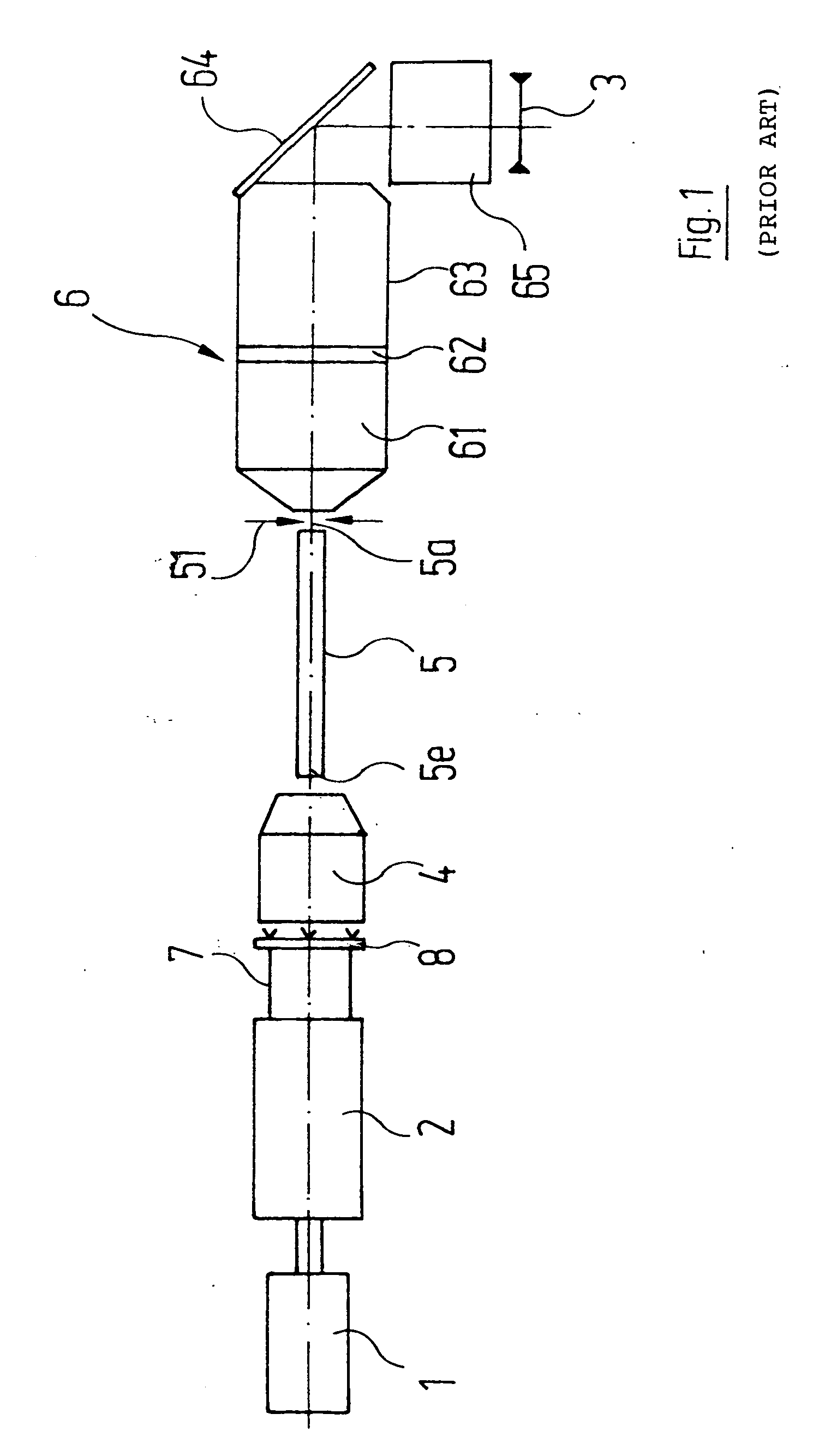
[0029]FIG. 1 shows a prior art illumination system for a projection exposure apparatus. The illumination system presets and forms a projection light bundle that illuminates a reticle 3. The reticle 3 contains an original structure which projected onto a wafer by means of projection optics (not shown in FIG. 1).

[0030] A laser 1 is used as source for projection light. It generates a projection light bundle 7 which is represented in FIG. 1 in certain regions only. The projection light bundle 7 is firstly expanded in the optical path downstream of the laser 1 by means of a zoom objective 2. Subsequently the projection light bundle 7 passes through a diffractive optical element 8 and an objective 4 which directs the projection light bundle 7 onto an entrance face5e of a glass rod 5. The latter mixes and homogenizes the projection light bundle 7 as a result of multiple internal reflections. Located in the region of the exit face 5a of the glass rod 5 is a field plane of the illumination ...


PUM


Abstract

An optical apparatus for illuminating an object, for example an illumination system of a microlithographic exposure system, comprises a light source that generates a plurality of individual bundles that constitute an illumination bundle. A control device controls the light source in such a way that a desired form of the illumination bundle is determined by selecting an appropriate set of individual bundles.

Description

CROSS-REFERENCE TO RELATED APPLICATIONS [0001] This application is a continuation (and claims the benefit of priority under 35 U.S.C. §120) of international application number PCT / EP2003 / 006397, filed Jun. 18, 2003 which claims priority to German application number 102 30 652.4, filed Jul. 8, 2002. The disclosure of the prior applications are considered part of (and is incorporated by reference in) the disclosure of this application. BACKGROUND OF THE INVENTION [0002] 1. Field of the Invention [0003] The present invention relates generally to an optical apparatus for illuminating an object. More particularly, the invention relates to illumination systems used in microlithographic exposure apparatuses. Such apparatuses are suitable for microlithographic chip manufacture or for the production of flat display screens, for example. [0004] 2. Description of Related Art [0005] U.S. Pat. No. 5,091,744 A discloses an illumination system of a projection exposure apparatus in which a pluralit...

Claims


Application Information

Patent Timeline
IPC IPC(8): G02B19/00G02B27/00G03F7/20H01L21/027
CPCG03F7/70141G03F7/70116
Inventor BADER, DIETERRENG, NORBERTWANGLER, JOHANNES
Owner CARL ZEISS SMT GMBH
Why Eureka
Try Eureka