System and method for surgical instrument disablement via image-guided position feedback

a position feedback and surgical instrument technology, applied in the field of computer assisted surgery, can solve the problems of inconvenient operation, inconvenient operation, and inability to perform the operation, and achieve the effect of reducing the risk of infection and cosmetic deformity, and avoiding the use of system components

Inactive Publication Date: 2005-10-13
VANDERBILT UNIV
View PDF37 Cites 73 Cited by
  • Summary
  • Abstract
  • Description
  • Claims
  • Application Information

AI Technical Summary

Benefits of technology

[0020] In a further aspect, the present invention relates to a method for selectively disabling a surgical instrument operating in a surgical site of a region of interest of a living subject, where the surgical instrument has a distal end portion and is operable by a surgeon during a surgery. In one embodiment, the method includes the steps of intra-operatively tracking the visual line of sight of the surgeon and a location of the distal end por

Problems solved by technology

These systems have found limited use due to logistic difficulties including the exorbitant cost of a dedicated CT or MR imaging system in an operative suite and the physically confined environment in which a surgeon operates.
While accuracy with such systems is impressive [6, 7], it does involve the invasive placement of bone screws with small, yet real, risk of infection and cosmetic deformity.
Such systems have shown decreased accuracy that is unacceptable in otologic applications [8].
The cholesteatoma contains keratinizing squamous epithelium (skin) trapped within the middle ear cavity and leads to chronic infe

Method used


Image

  • System and method for surgical instrument disablement via image-guided position feedback
  • System and method for surgical instrument disablement via image-guided position feedback
  • System and method for surgical instrument disablement via image-guided position feedback

Examples


Embodiment Construction

[0032] The present invention is more particularly described in the following examples that are intended as illustrative only since numerous modifications and variations therein will be apparent to those skilled in the art. Various embodiments of the invention are now described in detail. Referring to the drawings, like numbers indicate like parts throughout the views. As used in the description herein and throughout the claims that follow, the meaning of “a,”“an,” and “the” includes plural reference unless the context clearly dictates otherwise. Also, as used in the description herein and throughout the claims that follow, the meaning of “in” includes “in” and “on” unless the context clearly dictates otherwise.

[0033] The description will be made as to the embodiments of the present invention in conjunction with the accompanying drawings 1-6. In accordance with the purposes of this invention, as embodied and broadly described herein, this invention, in one aspect, relates to a syste...


PUM


Abstract

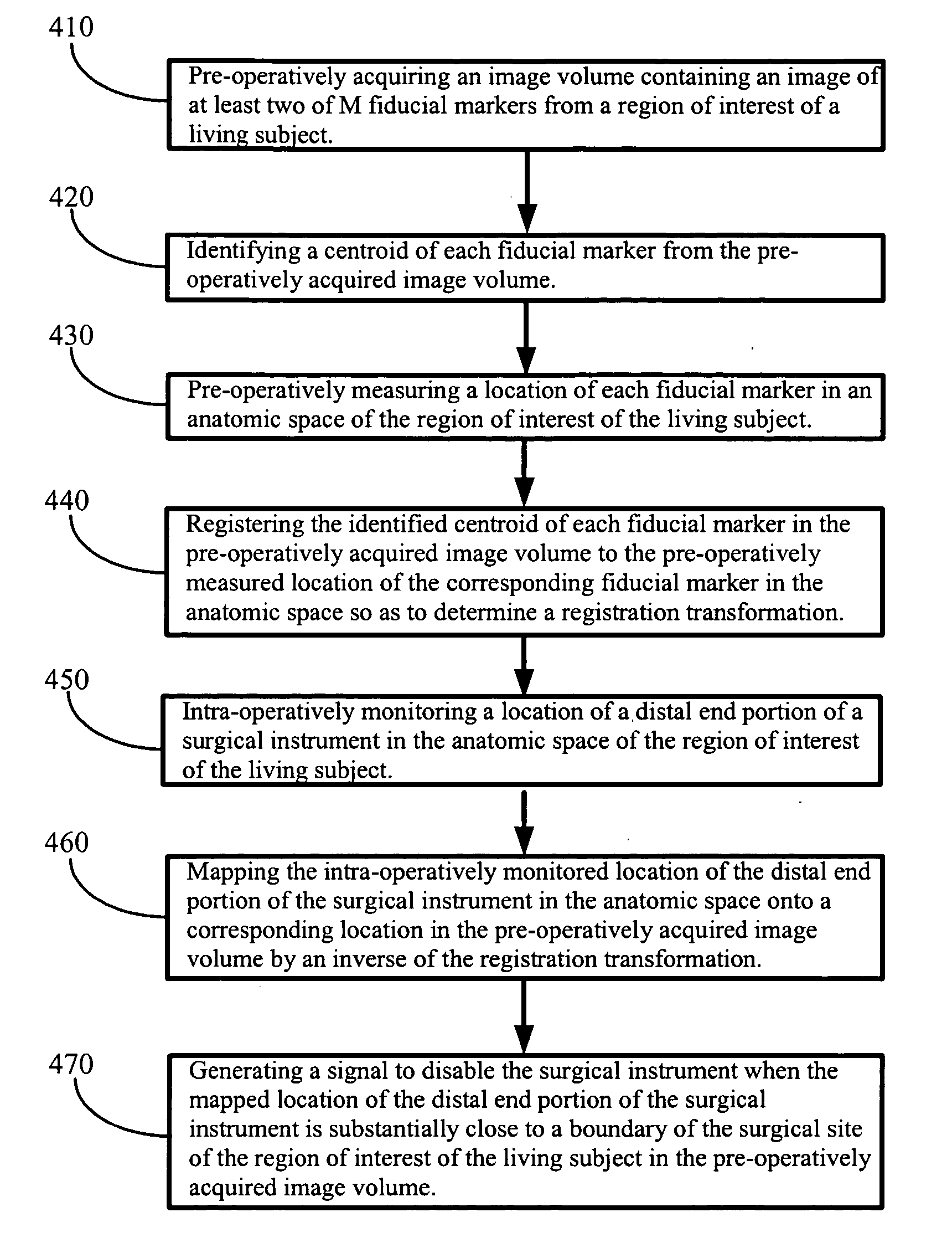
A system for selectively disabling a surgical instrument operating in a surgical site of a region of interest of a living subject. In one embodiment, the system includes means for noninvasively placing a number of fiducial markers in an anatomic space of the region of interest of the living subject, means for pre-operatively measuring a location of each fiducial marker in the anatomic space, an imaging acquisition device for pre-operatively acquiring an image volume from the region of interest of the living subject, a probe for intra-operatively monitoring a location of the surgical instrument in the anatomic space, and a controller configured to perform the steps of identifying a centroid of each fiducial marker in the image volume, registering the identified centroid of each fiducial marker in the image volume to the measured location of the corresponding fiducial marker in the anatomic space to determine a registration transformation, mapping the monitored location of the surgical instrument in the anatomic space onto a corresponding location in the image volume by an inverse of the registration transformation, and generating a signal to disable the surgical instrument when the mapped location of the surgical instrument is substantially close to a boundary of the surgical site of the region of interest in the image volume.

Description

CROSS-REFERENCE TO RELATED PATENT APPLICATION [0001] This application claims the benefit, pursuant to 35 U.S.C. § 119(e), of provisional U.S. patent application Ser. No. 60 / 555,377, filed Mar. 22, 2004, entitled “SURGICAL INSTRUMENT DISABLEMENT VIA IMAGE-GUIDED POSITION FEEDBACK,” by Robert F. Labadie, and J. Michael Fitzpatrick, which is incorporated herein by reference in its entirety. [0002] Some references, which may include patents, patent applications and various publications, are cited and discussed in the description of this invention. The citation and / or discussion of such references is provided merely to clarify the description of the present invention and is not an admission that any such reference is “prior art” to the invention described herein. All references cited and discussed in this specification are incorporated herein by reference in their entireties and to the same extent as if each reference was individually incorporated by reference. In terms of notation, here...

Claims


Application Information

Patent Timeline
IPC IPC(8): A61B5/05A61B17/00A61B17/24A61B19/00
CPCA61B17/24A61B2019/5483A61B19/46A61B19/50A61B19/52A61B19/5244A61B19/54A61B2017/00022A61B2017/00035A61B2017/00057A61B2017/00106A61B2017/00123A61B2017/00216A61B2019/204A61B2019/262A61B2019/4805A61B2019/481A61B2019/5229A61B2019/5236A61B2019/5251A61B2019/5255A61B2019/5272A61B2019/5287A61B2019/5289A61B2019/5454A61B19/20A61B2090/3983A61B90/10A61B90/16A61B2090/502A61B90/36A61B2034/2055A61B2034/2072A61B2090/363A61B2090/364A61B2090/0801A61B90/06A61B2090/08021A61B34/10A61B2090/372A61B2090/374A61B34/20A61B2034/2051A61B90/39A61B2090/3954
Inventor LABADIE, ROBERT F.FITZPATRICK, J. MICHAEL
Owner VANDERBILT UNIV
Why Eureka
Try Eureka