Osteoconductive integrated spinal cage and method of making same

Inactive Publication Date: 2005-10-13
SPINAL ELEMENTS INC
View PDF24 Cites 114 Cited by
  • Summary
  • Abstract
  • Description
  • Claims
  • Application Information

AI Technical Summary

Benefits of technology

[0018] In accordance with a further aspect of the present invention, there is provided a spinal cage. The cage comprises a structural component having sufficient strength to withstand the compres

Problems solved by technology

Additionally back and spinal musculoskeletal impairments are the leading cause of lost work productivity in the US according to a 1999 study of the American Academy of Orthopaedic Surgeons.
The bone harvest procedure is generally called iliac crest bone harvest, and it often results in donor site morbidity.
According to a study published in the Journal Spine, 50.7% of patients who underwent the bone graft procedure experienced a significan

Method used


Image

  • Osteoconductive integrated spinal cage and method of making same
  • Osteoconductive integrated spinal cage and method of making same
  • Osteoconductive integrated spinal cage and method of making same

Examples


example 1

Spinal Cage Made by Heat Staking of HA Osteoconductive Component into PEKK Structural Component

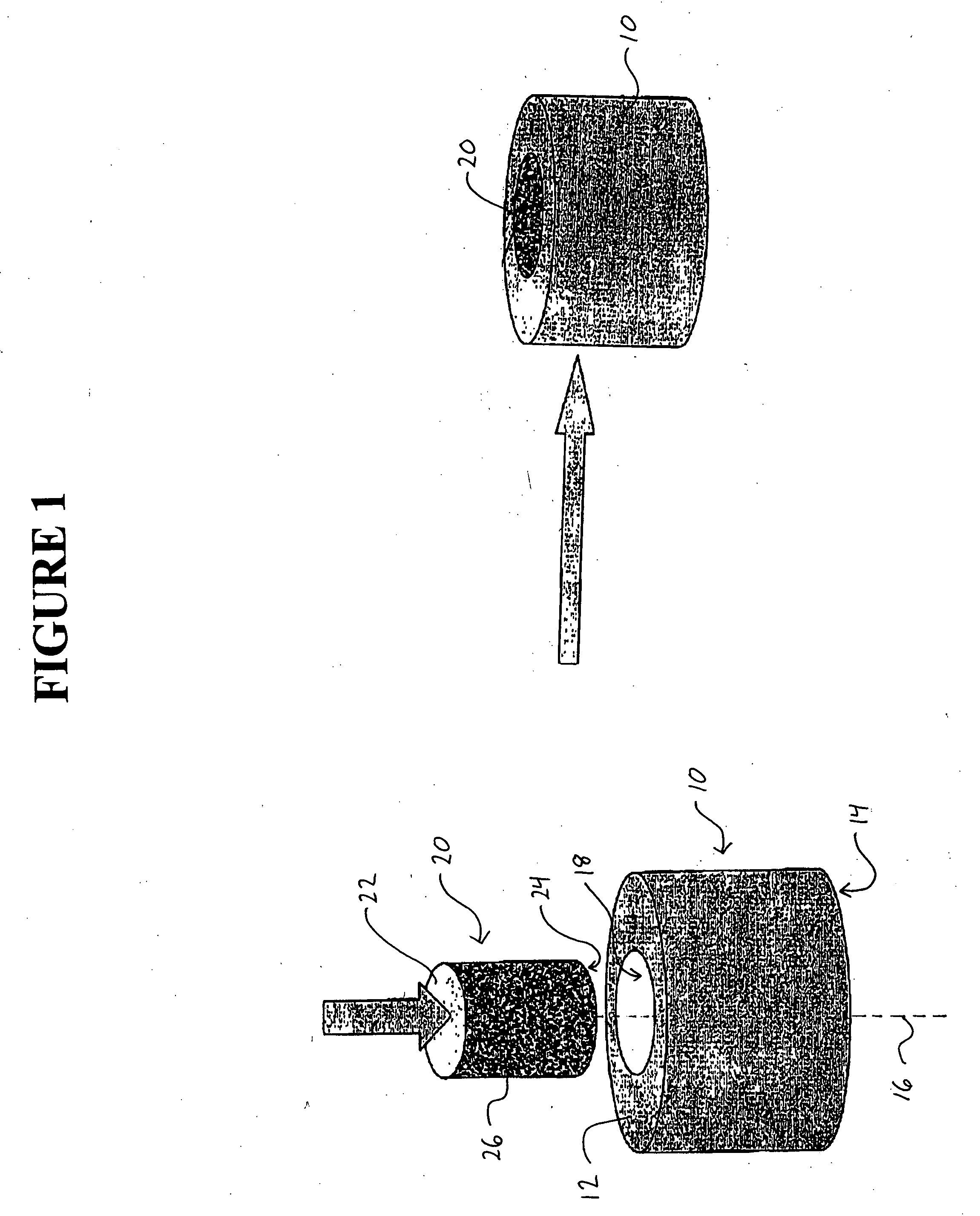
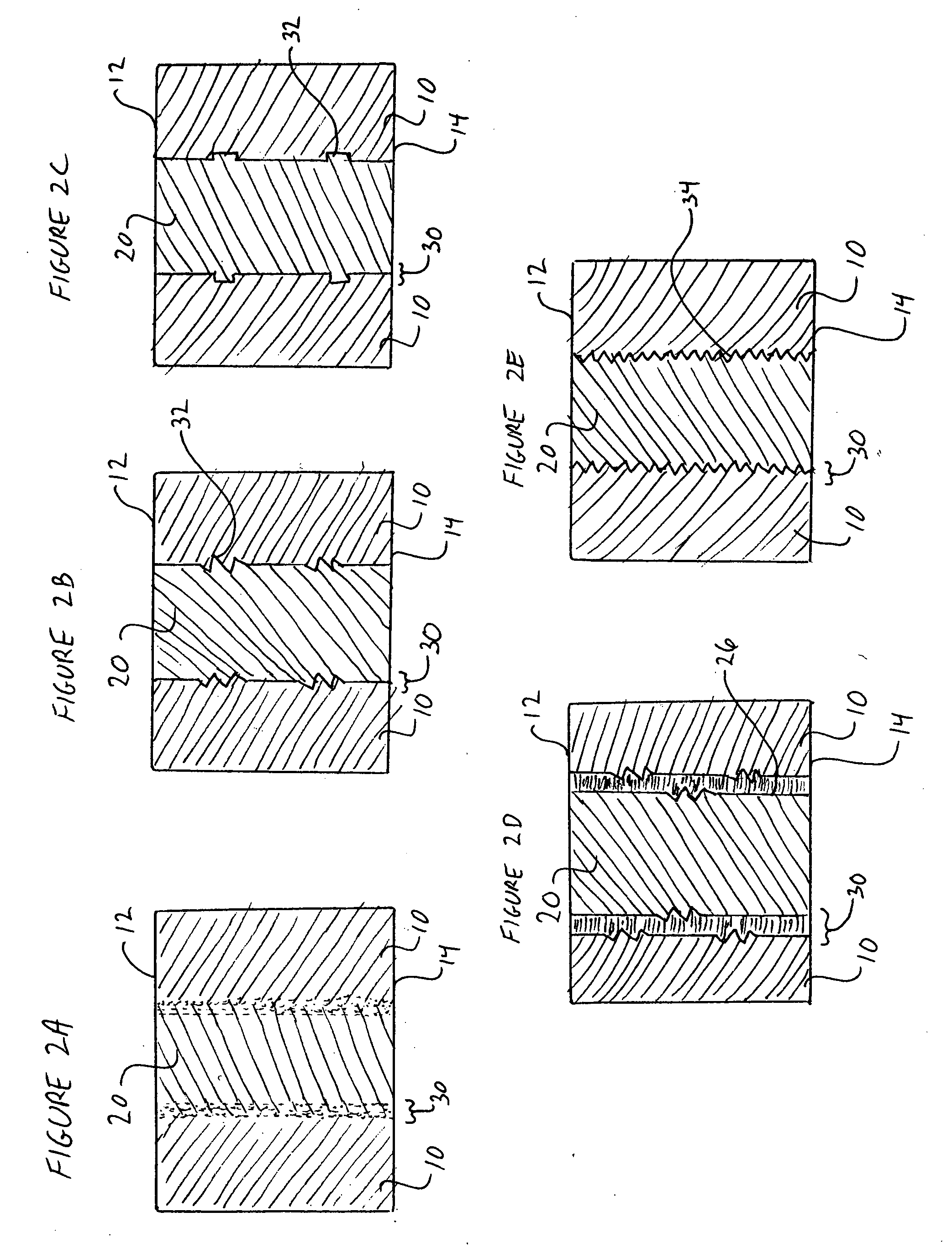
[0061] One of several manufacturing methods used to join the osteoconductive portion with the polymer structural component includes heat staking. In this example, the osteoconductive material is preferably composed of a substance(s) that can be heated to above the melting temperature of the polymer without significant degradation. Osteoconductive materials that may be used in this method include ceramics such as porous hydroxyapatite (HA) and calcium phosphate. The HA component must be slightly larger than the polymer component so that when inserted a slight interference fit is developed such that mechanical forces will prevent the two from separating. To use heat staking as the joining method, one must preheat the osteoconductive portion significantly above the melting temperature of the structural polymer component. For example, using PEKK polymer, one must preheat the HA osteoconductiv...

example 2

Over Molding PEEK Polymer Over Tri-Calcium Phosphate

[0062] In this example, the PEEK polymer is the structural component of the spinal cage, and tri-calcium phosphate is the osteoconductive portion of the spinal cage. A mold designed to create the proper shape for intervertebral implantation, restoration of disc height, and over molding of the tri-calcium phosphate portion. In this case, the tri-calcium phosphate actually makes up the interior surfaces of the polymer mold. The tri-calcium phosphate is designed such that there is a mechanical locking caused between the polymer and tri-calcium phosphate (TCP). For example, the TCP component can be shaped such that it has small apertures or appendages that the polymer is formed into or around when it is melted over the surface. The preferred method for melting the polymer in a mold around the TCP is injection molding, however, compression molding may also work. This over molding process includes inserting the TCP into the mold and hol...

example 3

Snap Fit of Resorbable Polymer onto Titanium Spinal Cage

[0063] In this example, a resorbable polymer such as polyglycolic acid (PGA) is used to form the osteoconductive portion of the spinal cage, and titanium is used for the structural component. In this method, clinically superior results may be achieved if the resorbable polymer is porous and filled with a small amount of calcium sulfate. The resorbable polymer shape is designed such that it includes a flexible snap for incorporating with the titanium structural component. Substantial design freedom exists in this instance. In general, snap fits may be achieved by providing an extension on one of the two components which is received within a complementary recess on the other of the two components. The titanium can make up the interior, exterior, or even side portion of the cage in order to cause bone growth through out the inter-vertebral space.


PUM

PropertyMeasurementUnit
Compressive strengthaaaaaaaaaa
Sizeaaaaaaaaaa
Strengthaaaaaaaaaa

Abstract

The spinal cage comprises a structural component having sufficient strength to withstand the compressive loading between vertebral bodies. The structural component is integrated with an osteoconductive component to facilitate bone growth between the vertebral bodies. The structural component may comprise any of PEEK, PEKK, or other structural material. The osteoconductive component may comprise any of allograft, natural bone, tricalcium phosphate, hydroxyapatite or a blend of calcium carbonate, calcium lactate and other calcium salts. A method for making the spinal cage involves molding polymers around an osteoconductive component, heat staking, and may further include ultrasonically welding, snap fit or mechanically assembling and/or adhesively bonding components.

Description

RELATED APPLICATION DATA [0001] This application claims priority under 35 U.S.C. § 119(e) from provisional application Ser. No. 60 / 523,288 filed Nov. 18, 2003, the disclosure of which is incorporated in its entirety herein by reference.BACKGROUND OF THE INVENTION [0002] The present invention is directed to a spinal cage for use in spine surgery, and more particularly, is directed to an osteoconductive integrated spinal cage that may be made from a variety of materials, including PEKK, PEEK, porous hydroxyapatite, etc. [0003] Back or spinal musculoskeletal impairments represent just over half of reported musculoskeletal impairments in the US. Additionally back and spinal musculoskeletal impairments are the leading cause of lost work productivity in the US according to a 1999 study of the American Academy of Orthopaedic Surgeons. According to the same study, 4.4 million people report inter-vertebral disc problems in the US. Although most patients recover using non-surgical therapies, ...

Claims


Application Information

Patent Timeline
IPC IPC(8): A61F2/00A61F2/02A61F2/28A61F2/30A61F2/44A61L27/46A61L27/48A61L27/56B29C43/56
CPCA61F2/28B29L2031/7532A61F2/4465A61F2002/2835A61F2002/30029A61F2002/30034A61F2002/30062A61F2002/30065A61F2002/30133A61F2002/30224A61F2002/30235A61F2002/3024A61F2002/30354A61F2002/30405A61F2002/30448A61F2002/30449A61F2002/30457A61F2002/30487A61F2002/30489A61F2002/30535A61F2002/30957A61F2210/0004A61F2210/0071A61F2220/0025A61F2220/0033A61F2220/005A61F2220/0058A61F2230/0015A61F2230/0069A61F2250/0031A61F2250/0058A61F2310/00017A61F2310/00023A61F2310/00293A61L27/46A61L27/48A61L27/56A61L2430/38B29C43/56B29C2043/3266B29C2043/3636A61F2/3094A61F2002/30028A61F2002/30032A61F2002/30451
Inventor ANDRES, TODD
Owner SPINAL ELEMENTS INC
Why Eureka
Try Eureka