Sputter target material and method of producing the same

a target material and sputtering technology, applied in the direction of diaphragms, metallic material coating processes, metal-working apparatuses, etc., can solve the problems of affecting affecting the work efficiency of plastics, and affecting the quality of plastics, etc., to achieve the effect of improving the workability of plastics

Inactive Publication Date: 2005-10-20
HITACHI METALS LTD
View PDF1 Cites 54 Cited by
  • Summary
  • Abstract
  • Description
  • Claims
  • Application Information

AI Technical Summary

Benefits of technology

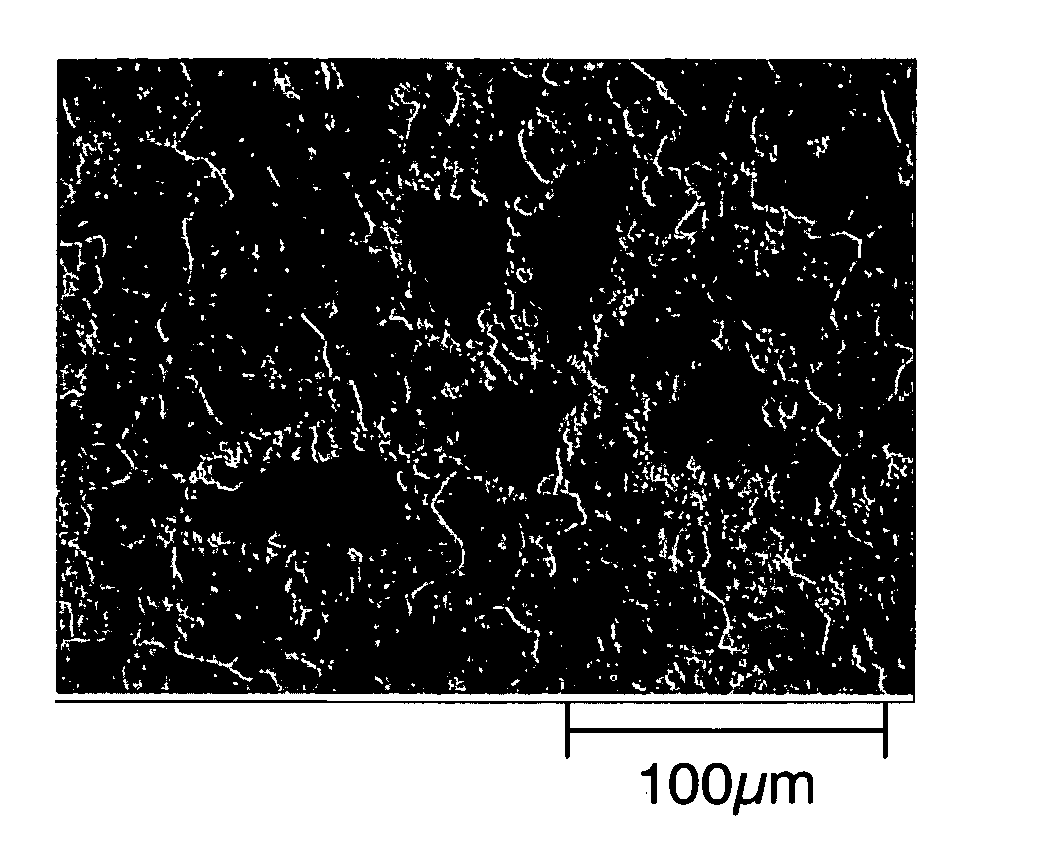
[0010] The present inventors carried out various researches on the above problems, and found a solution of the process that a powder blend consisting of powders of Mo and an additive metal element(s) M is prepared, the powder blend is compressed to produce a green compact, and the green compact of the powder is sintered to obtain a sintered product whereby making the additive metal element M, which is capable of fixing oxygen in the Mo matrix, to be quite finely dispersed in the Mo matrix, the sintered product having a metal structure in which oxygen in the Mo matrix is fixed around the element M. It was found also that the sintered product is improved in plastic workability by such oxygen fixing around the metal element M.
[0021] According to the invention Mo alloy sputter target material, a component segregation in the Mo alloy sputter target material is restrained, it is possible to improve the component uniformity of thin films formed from the Mo alloy sputter target material by sputtering, and the Mo alloy sputter target material has improved plastic workability.

Problems solved by technology

According to this method, particles of the additive element(s) in the blend powder are liable to agglomerate with one another.
Thus, there arises a problem that a segregation of alloy components occurs after sintering resulting in that a thin film formed from the sintered material by sputtering has not a uniform distribution of component elements.
Another problem is that when the sintered material is subjected to plastic working, defects such as cracking are liable to occur due to the segregation of component elements.

Method used


Image

  • Sputter target material and method of producing the same
  • Sputter target material and method of producing the same
  • Sputter target material and method of producing the same

Examples


example 1

[0048] There were prepared a Mo powder having an average particle size of 6 μm, a Nb powder having an average particle size of 100 μm, a Cr powder having an average particle size of 100 μm, a Ti powder having an average particle size of 100 μm, a Zr powder having an average particle size of 100 μm, and a V (vanadium) powder having an average particle size of 100 μm.

[0049] Invention Specimen Nos. 1 to 6 target materials shown in Table 1 were produced by the following process.

[0050] (1) In order to produce each of the specimens, given amounts in atomic % of the Mo powder and any one of the additive element powder were checkweighed.

[0051] (2) The checkweighed powders were blended for 10 minutes with utilization of a V-type blender to obtain a raw material powder.

[0052] (3) The raw material powder was compressed by a CIP machine to form a green compact.

[0053] (4) The green compact was pulverized with utilization of a jaw crusher and a disc mill to produce a secondary powder.

[0054]...

example 2

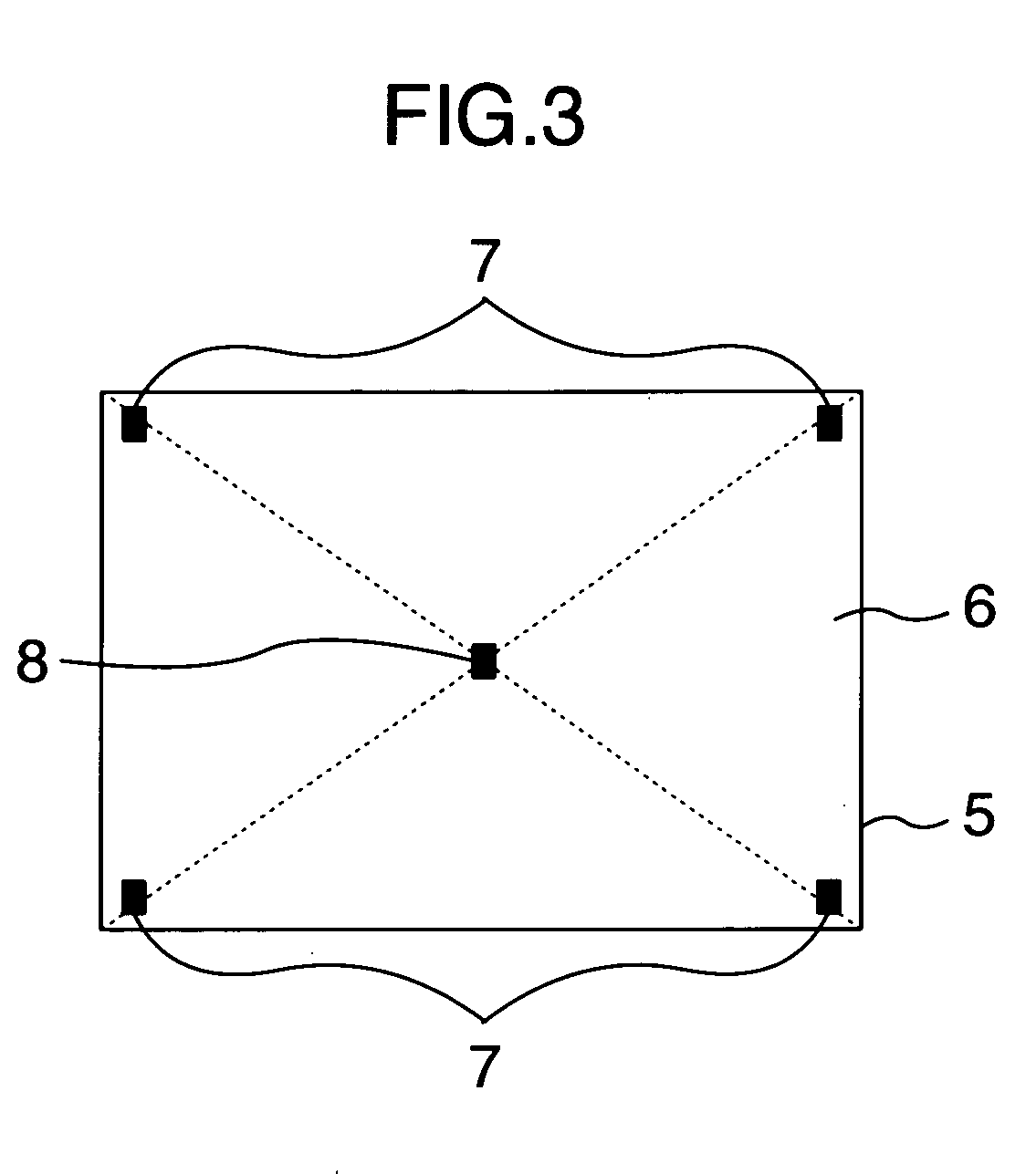
[0070] Sintered bodies, having the same chemical compositions and the same sizes as those produced in Example 1, respectively, were produced by the same manner as the case of Example 1, and subsequently subjected to hot rolling. The hot rolling after the HIP process was carried out for the respective sintered body, as contained in the pressurizing container without removing the container from the sintered body, such that a working process of heating up to a temperature of 1150° C. and rolling under a reduction ratio of not more than 50% was repeated five times. An aimed rolling reduction ratio was 25%. After hot rolling, the respective work was sliced and machined to obtain a sputter target material having a rectangular form and a measurement of a thickness of 10 mm, a width of 1130 mm and a length of 1200 mm. As in the case of Example 1, five test pieces were taken from each of the specimen sputtering target materials, each of which has a section perpendicular to the sputtering sur...


PUM

PropertyMeasurementUnit
surface areaaaaaaaaaaa
side lengthaaaaaaaaaa
particle sizeaaaaaaaaaa

Abstract

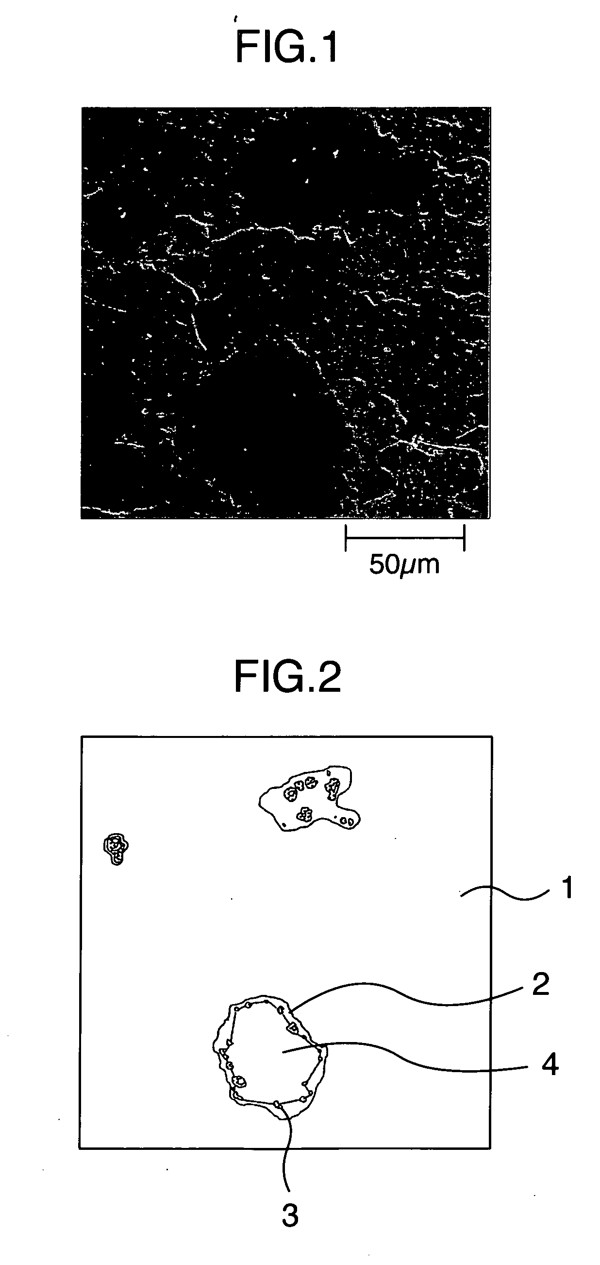
A sputter target material which is of a sintered material, wherein the sputter target material consists of 0.5 to 50 atomic % in total of at least one metal element (M) selected from the group of Ti, Zr, V, Nb and Cr, and the balance of Mo and unavoidable impurities, and has a microstructure seen at a perpendicular cross section to a sputtering surface, in which microstructure oxide particles exist near a boundary of each island of the metal element (M), and wherein the maximum area of the island, which is defined by connecting the oxide particles with linear lines so as to form a closed zone, is not more than 1.0 mm2.

Description

BACKGROUND OF THE INVENTION [0001] The present invention relates to a sputter target material, more particularly to a sputter target material used for forming Mo alloy thin films which are used as electrical wiring, electrodes and so on in flat panel display devices, and a method of producing the same. DESCRIPTION OF THE RELATED ART [0002] Presently, films of a refractory metal, e.g. Mo, which have low electrical resistance, are broadly used for thin film electrodes and thin film wiring in liquid crystal displays (herein referred to as LCDs) which are one type of flat panel display devices. Since these thin-film electrodes, thin-film wiring, etc. are required to have heat-resistance and corrosive resistance properties during producing the thin film, there is a tendency to favorably use Mo alloys containing additive Cr or W, for example. [0003] In general, when the Mo alloys are used to form wiring, the sputtering method is carried out with utilization of a target material having the...

Claims


Application Information

Patent Timeline
Patent Type & Authority Applications(United States)
IPC IPC(8): B22F1/00B22F3/14C22C1/04C22C27/04C23C14/14C23C14/32C23C14/34
CPCB22F2998/10C22C1/045C23C14/3414B22F1/0003B22F1/0096B22F3/14B22F1/09B22F1/148C22C27/04
Inventor INOUE, KEISUKEFUKUI, TSUYOSHITANIGUCHI, SHIGERUUEMURA, NORIOIWASAKI, KATSUNORISAITOH, KAZUYA
Owner HITACHI METALS LTD
Why Eureka
Try Eureka