Compound laser beam welding

a laser beam and compound technology, applied in welding/soldering/cutting articles, metal working devices, manufacturing tools, etc., can solve the problems embrittlement or hot cracking along weld joints, and the problem of hot cracking of weld nuggets remains. , to achieve the effect of reducing shrinkage stresses and reducing shrinkage stresses in the welded hem assembly

Inactive Publication Date: 2005-10-20
SUZUKI MOTOR CORP +1
View PDF8 Cites 13 Cited by
  • Summary
  • Abstract
  • Description
  • Claims
  • Application Information

AI Technical Summary

Benefits of technology

[0008] The effect of variation in compound laser beam power with welding period interval is to produce a resulting variation in the size or configuration of the weld nugget along the continuous weld path, and consequently reduce the shrinkage stresses in the welded hem assembly. During the 200 ms intervals of high compound beam power, the linear weld nugget segments are relatively wide and deep. During the shorter intervening low beam power intervals, with only CO2 beam power, the linear weld nugget segments are narrower and shallower. It is found that this pattern of varying weld nugget configurations varies the cooling pattern of the weld pools and produces weld segments that are free of hot cracking and significantly reduces the shrinkage stresses.

Problems solved by technology

But a disadvantage is that the weld nugget formed in this rapid manner often exhibits embrittlement or hot cracking along the weld joint, especially in light metal alloys with relatively high thermal conductivity.
Efforts are made to control the energy level and / or the path of the laser to produce a puddle of weld metal of suitable shape to reduce embrittlement of the weld nugget, but in many laser welding applications porosity and / or hot cracking of the weld nugget remains as a problem.

Method used


Image

  • Compound laser beam welding
  • Compound laser beam welding
  • Compound laser beam welding

Examples


Embodiment Construction

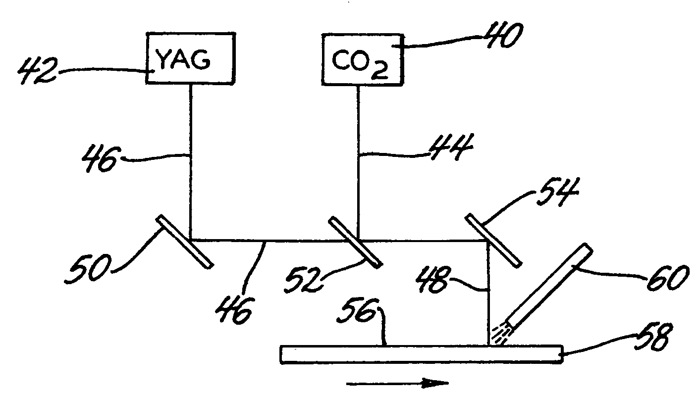
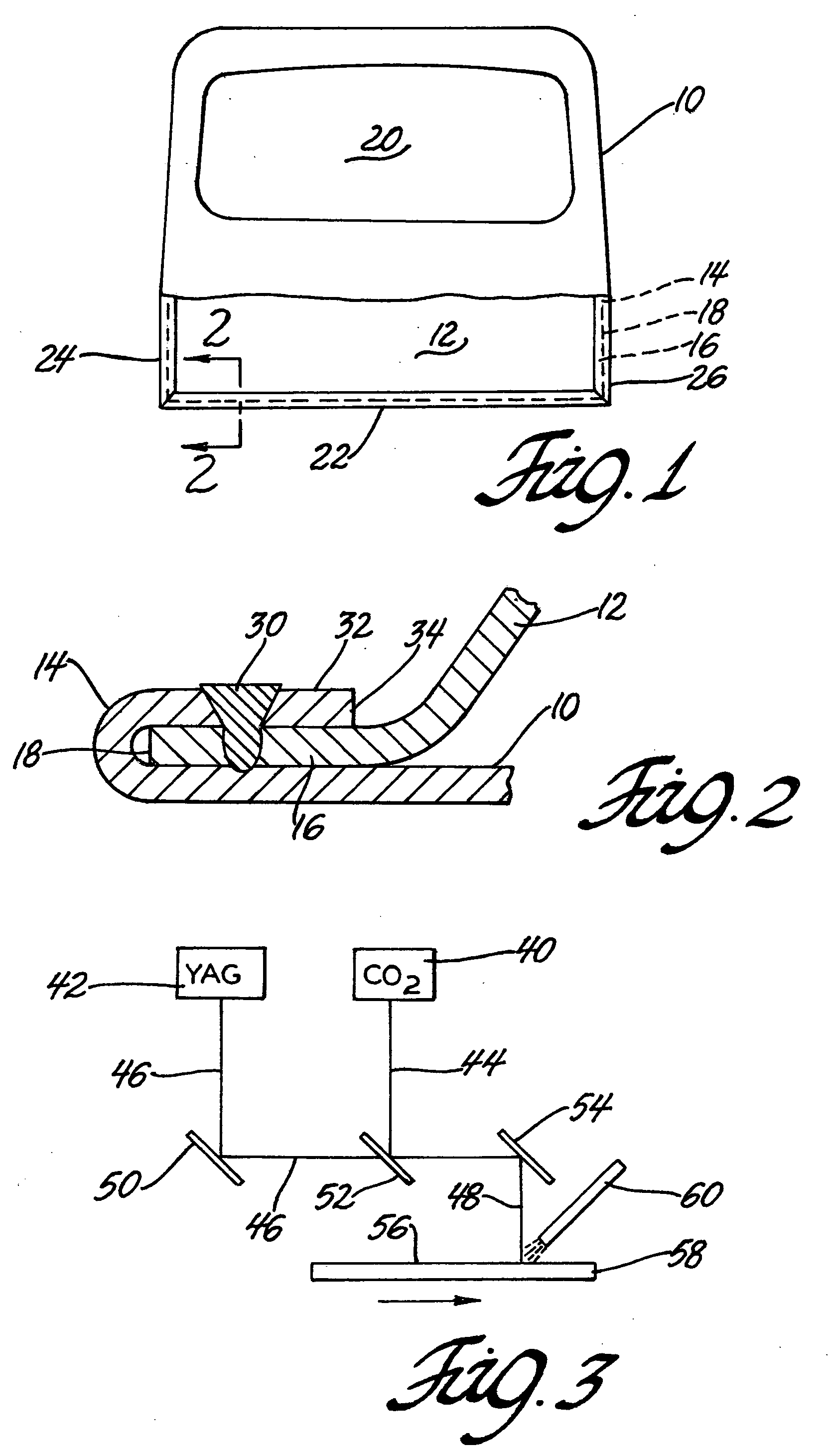
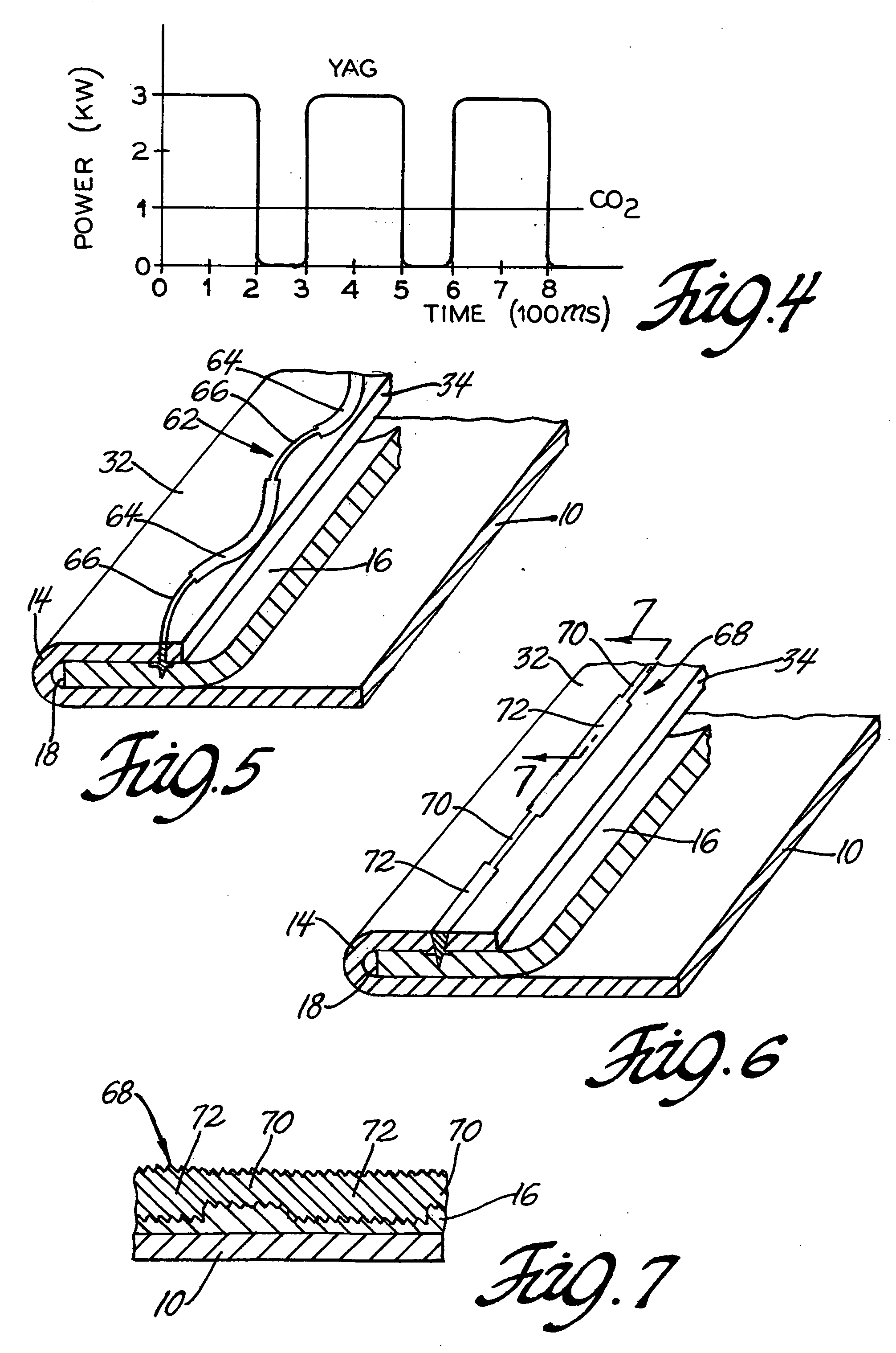
[0018] The coherent and focused energy of laser beams is used in metal machining, heat treatment and welding operations. In the metal welding applications, lasers are often used in welding two or more sheet metal layers. For example, flanges of metal sheets are joined by using a laser beam to melt through the thickness of the upper flange and into the lower flange of an assembly. The laser beam is usually moved relative to the workpiece to trace a linear path, straight or non-straight, along the flange area, or other area to be joined, and after the laser beam has moved along its path, molten metal solidifies by heat loss to the adjacent sheet material to form a weld nugget. There is always a desire to form laser welds faster, with greater accuracy and better process control.

[0019] There is also a desire to apply laser welding technology to joining light weight sheet metal parts, such as automotive vehicle body panels. But when laser welding is attempted on aluminum alloy panels it...


PUM

PropertyMeasurementUnit
thicknessaaaaaaaaaa
poweraaaaaaaaaa
frequencyaaaaaaaaaa

Abstract

Hot cracking in laser welds produced in metal workpieces, especially aluminum or magnesium sheet alloys, is avoided by suitably combining the beams of two different lasers, for example a CO2 laser and a YAG laser, into a compound beam that is moved along a weld path in the surface of the workpiece. The power level of at least one of the lasers is cyclically varied so that weld nugget segments of different alternating, hot crack free, configurations are produced in a linear weld.

Description

TECHNICAL FIELD [0001] This invention pertains to laser welding of metal alloys to avoid hot cracking at the weld site. More particularly, this invention pertains to laser welding of non-ferrous light metal alloys, such as aluminum or magnesium metal alloys, with laser radiation that is a compound beam combining two different laser sources. BACKGROUND OF THE INVENTION [0002] Metal workpieces are welded by directing a laser beam of suitable energy at a selected weld location on the surface of the metal. Some of the energy of the laser radiation is absorbed by the metal, melting the material at the region of incidence to a depth suitable to join the metal layers. After the laser beam is shut off or moved away along a weld path in the workpiece, the molten metal quickly dissipates heat to the surrounding unheated metal and re-solidifies to form a weld nugget between the layers to be joined. High power carbon dioxide (CO2) gas lasers and neodymium: YAG solid-state lasers, for example, a...

Claims


Application Information

Patent Timeline
Patent Type & Authority Applications(United States)
IPC IPC(8): B23K26/06B23K26/067B23K26/24B23K26/26B23K26/28B23K26/40B23K33/00
CPCB23K26/0604B23K26/246B23K2203/10B23K2201/18B23K33/00B23K26/244B23K2101/18B23K2103/10
Inventor WANG, PEI-CHUNGSAITOH, SHIGEKIMATSUDA, FUJIKOTAKESHI, MASAMISAITO, MASATAKE
Owner SUZUKI MOTOR CORP
Why Eureka
Try Eureka